
Motor-driven pump for pool or spa

a motor-driven pump and pool technology, applied in the direction of piston pumps, positive displacement liquid engines, liquid fuel engines, etc., can solve the problems of unsuitable or undesirable motor-driven pump configurations for some mounting locations, adversely affecting vibration, noise, and increased bearing wear, so as to achieve effective prevention of water leakage

Active Publication Date: 2006-02-21
ZODIAC POOL SYST LLC
View PDF18 Cites 50 Cited by
  • Summary
  • Abstract
  • Description
  • Claims
  • Application Information

AI Technical Summary

Benefits of technology

[0009]In accordance with the invention, an improved motor-driven pump is provided for circulating a flow of water in a swimming pool and / or spa environment or the like. The improved motor-driven pump comprises a drive motor contained within a motor housing having a seal plate mounted at one end thereof and carrying a shaft bearing for rotatably supporting an outwardly protruding drive shaft. An outboard end of the drive shaft is connected to an impeller disposed within a pump chamber defined cooperatively by the seal plate and a volute housing mounted thereon. The seal plate further supports multiple seal components for effectively preventing water leakage from the pump chamber and along the drive shaft into contact with the shaft bearing or drive motor.

Problems solved by technology

While such seal arrangements in motor-driven pumps have performed generally in a satisfactory manner, the inclusion of the extension bracket inherently results in a motor-driven pump configuration of extended length which may be unsuitable or undesirable for some mounting locations.
In addition, the extension bracket inherently requires the impeller on the drive shaft to be cantilevered a significant axial distance from the shaft bearing on the motor housing, wherein this cantilevered distance can adversely contribute to vibration, noise, and increased bearing wear.

Method used


Image

  • Motor-driven pump for pool or spa
  • Motor-driven pump for pool or spa
  • Motor-driven pump for pool or spa

Examples


Embodiment Construction

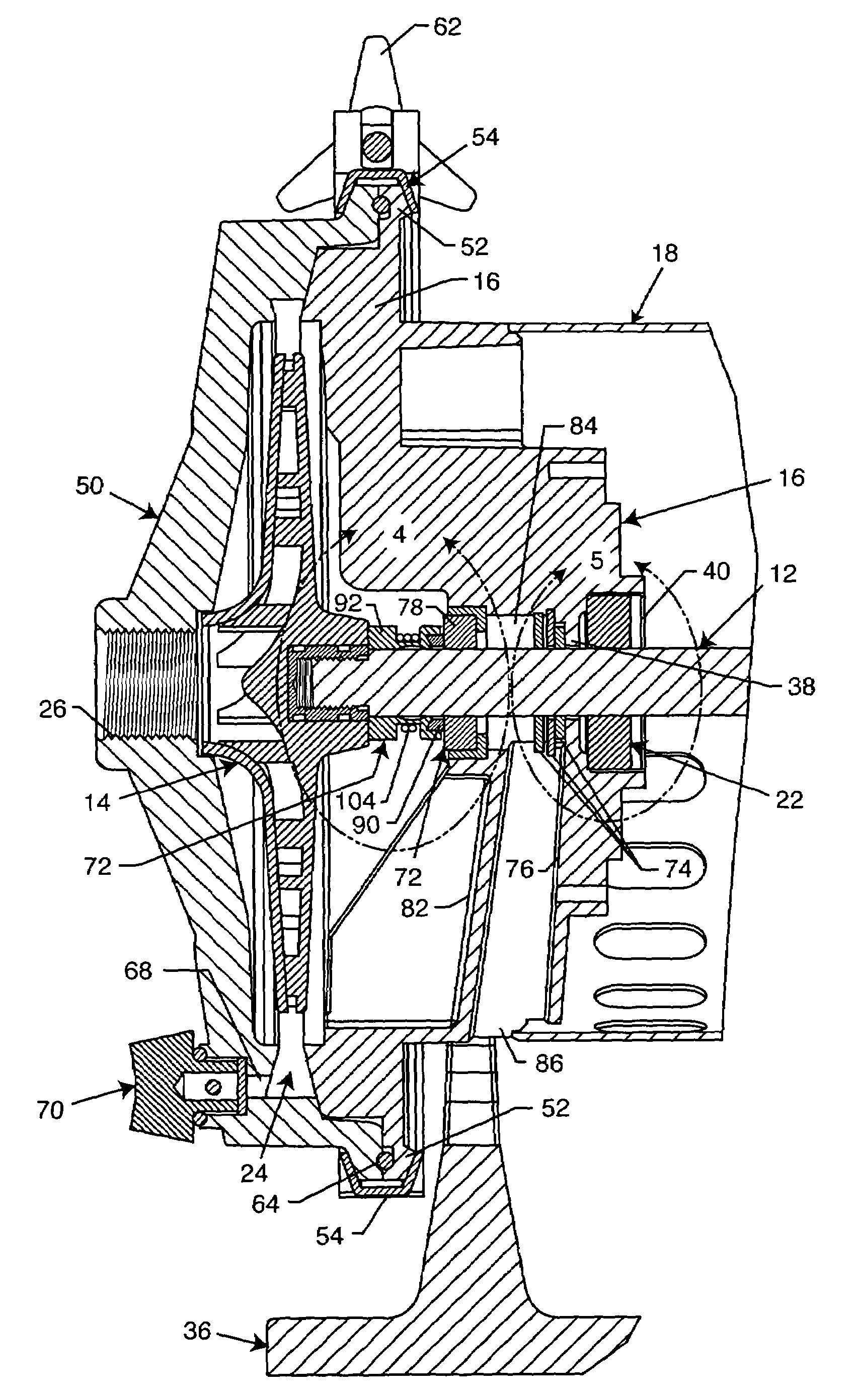
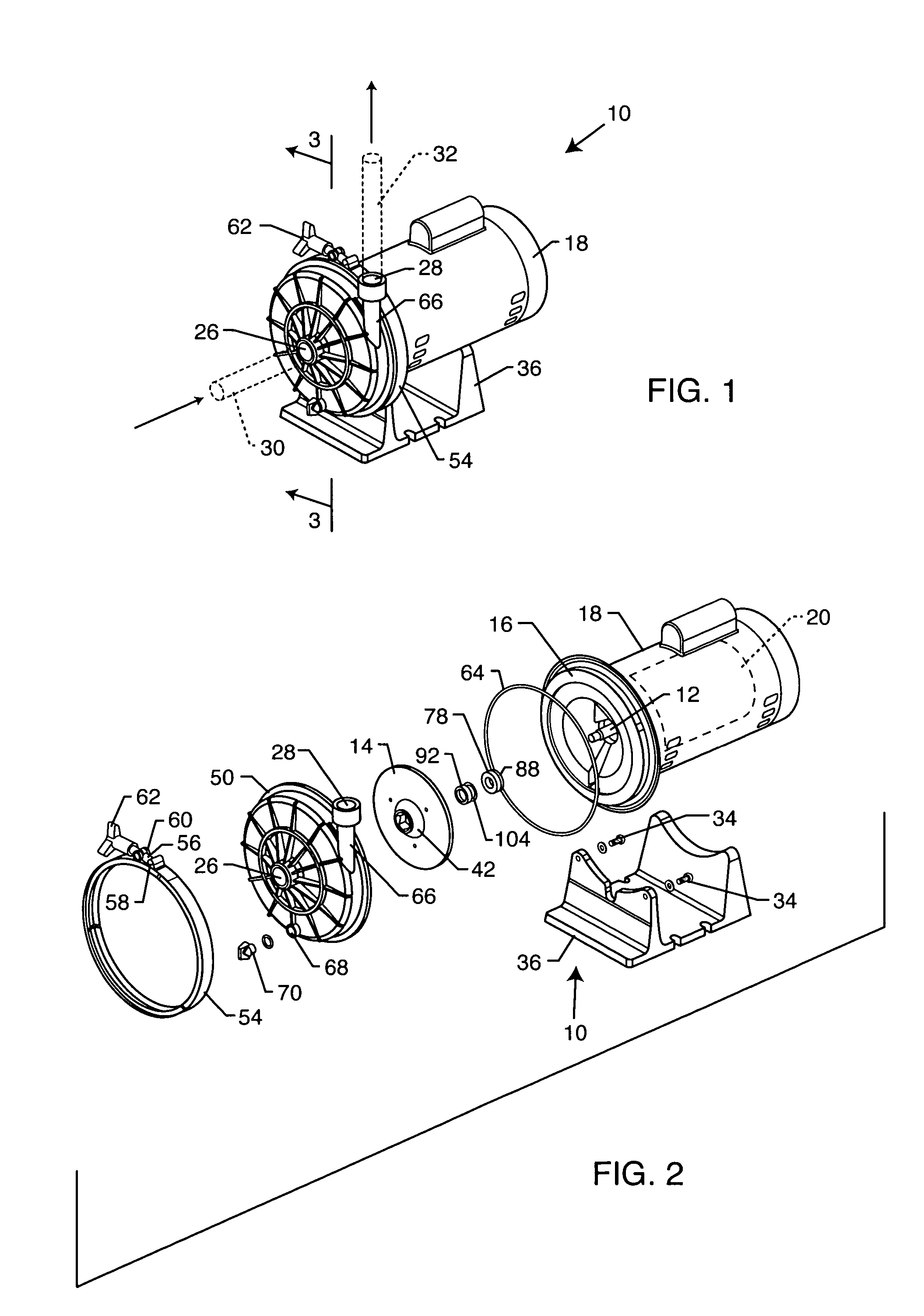
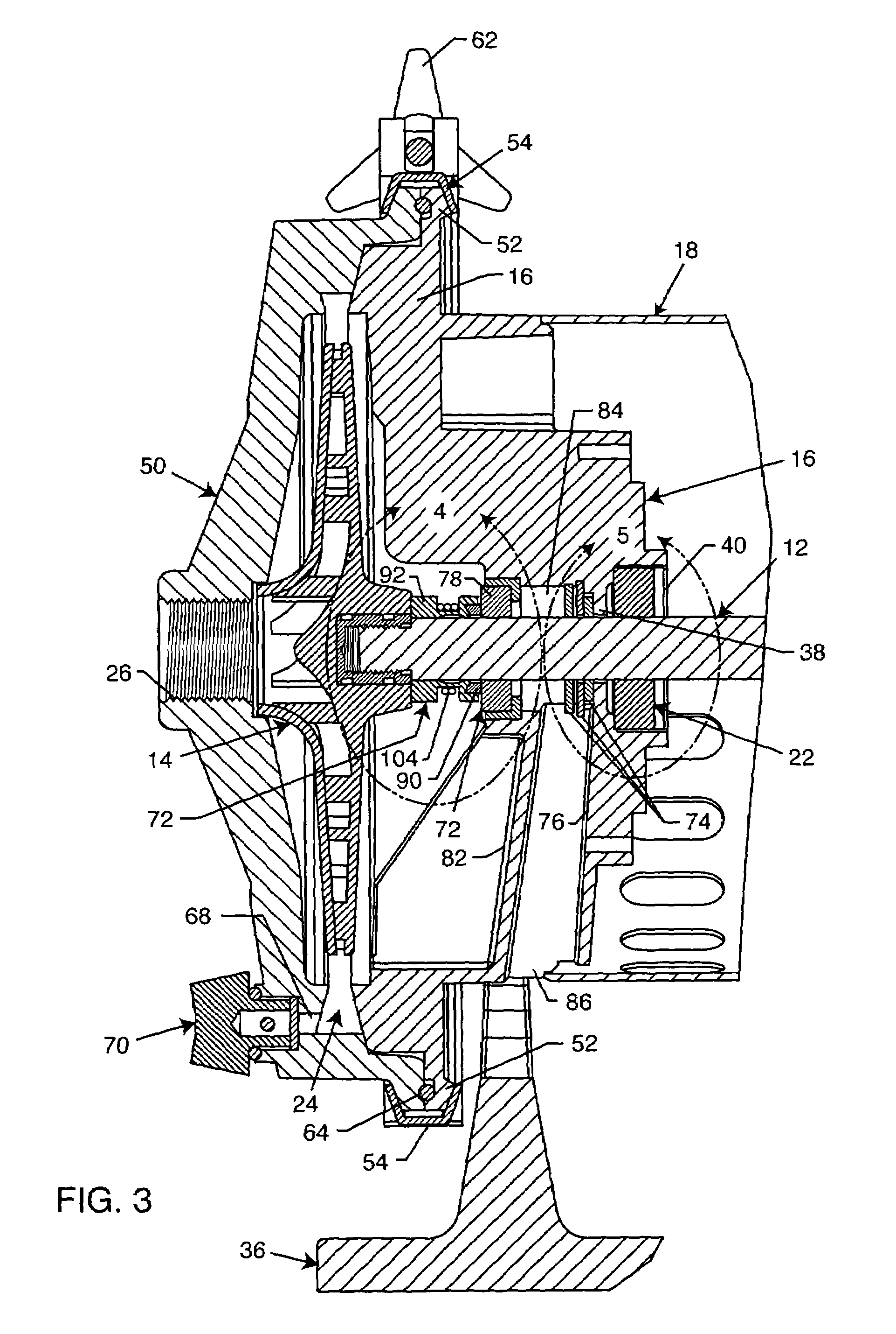
[0019]As shown in the exemplary drawings, an improved motor-driven pump referred to generally in FIGS. 1–3 by the reference numeral 10 is provided for circulating a flow of a liquid such as water in a swimming pool or spa environment or the like. The improved pump 10 incorporates a drive shaft 12 (FIGS. 2–4) for rotatably driving an impeller 14 to draw water from the pool and / or spa, and to pump or discharge the water under pressure to one or more items of pool equipment (not shown), such as a water filtration unit, or hydraulically driven pool cleaner device, or the like. In accordance with the invention, the improved pump 10 has a relatively compact and simplified construction to include a seal plate 16 (FIGS. 2–5) at one end of a motor housing 18, wherein this seal plate 16 supports multiple seal components for effectively safeguarding against water leakage into potentially damaging contact with a drive motor 20 (FIG. 2) encased within the motor housing 18, and / or with a shaft be...


PUM


Abstract

An improved motor-driven pump is provided for delivering a flow of water in a swimming pool or spa environment or the like. The improved pump includes a motor mounted within a motor housing having a seal plate mounted at one end thereof. The seal plate carries a shaft bearing for rotatably supporting a drive shaft having an outboard end connected to an impeller disposed within a pump chamber defined cooperatively by the seal plate and a volute housing mounted thereon. A primary seal assembly includes an axially spring-loaded dynamic seal ring carried on the drive shaft for rotation therewith and for running engagement with a stationary bushing carried by the seal plate. A secondary seal assembly is positioned axially between the primary seal assembly and motor bearing, and includes at least one slinger disk for radially outwardly slinging any water leaking past the primary seal assembly through a vent chamber.

Description

[0001]This application claims the benefit of copending U.S. Provisional Application 60 / 537,083, filed Jan. 16, 2004.BACKGROUND OF THE INVENTION[0002]This invention relates generally to improvements in motor-driven pumps of the type used, for example, for circulating water in a swimming pool or spa environment or the like. More particularly, this invention relates to an improved, relatively simplified and more compact pump of the type having a seal plate mounted at one end of a motor housing and adapted to support multiple seal components to prevent water leakage past the seal plate and into the motor housing.[0003]Motor-driven pumps for use with a swimming pool or spa are generally known in the art, wherein the pump is adapted to deliver a flow of water under pressure to one or more pool equipment items prior to recirculation of the water to the pool or spa. For example, modern swimming pool and / or spa facilities typically include a filtration unit containing an appropriate filter m...

Claims


Application Information

Patent Timeline
Patent Type & Authority Patents(United States)
IPC IPC(8): F04B17/03F04B17/00F04B35/04F04D29/10F04D29/12
CPCF04D29/126F04D29/106F05D2260/6022
Inventor PETERSON, JR., DAVID J.HAMZA, HASSANPETERSON, KENNETH A.WICHMANN, JEFFREY A.
Owner ZODIAC POOL SYST LLC
Learn More