Slip ring with connector pins

a technology of connector pins and slip rings, which is applied in the manufacture of brushes, current collectors, electrical equipment, etc., can solve the problems of ring failure, brush replacement, and inability to manufacture, reconfigure and replace,

Inactive Publication Date: 2006-02-21
UNIT INDS
View PDF18 Cites 12 Cited by
  • Summary
  • Abstract
  • Description
  • Claims
  • Application Information

AI Technical Summary

Problems solved by technology

As the rings rotate, the brushes ride and wear against the rings and eventually the brushes may have to be replaced.
Additionally, if the rings are thinly plated, they may eventually become worn to a degree that they must also be replaced.
Additionally, the rings of previous slip ring devices have been somewhat difficult to manufacture, reconfigure and replace due to the methods of assembly traditionally used in building slip ring assemblies.

Method used


Image

  • Slip ring with connector pins
  • Slip ring with connector pins
  • Slip ring with connector pins

Examples


Embodiment Construction

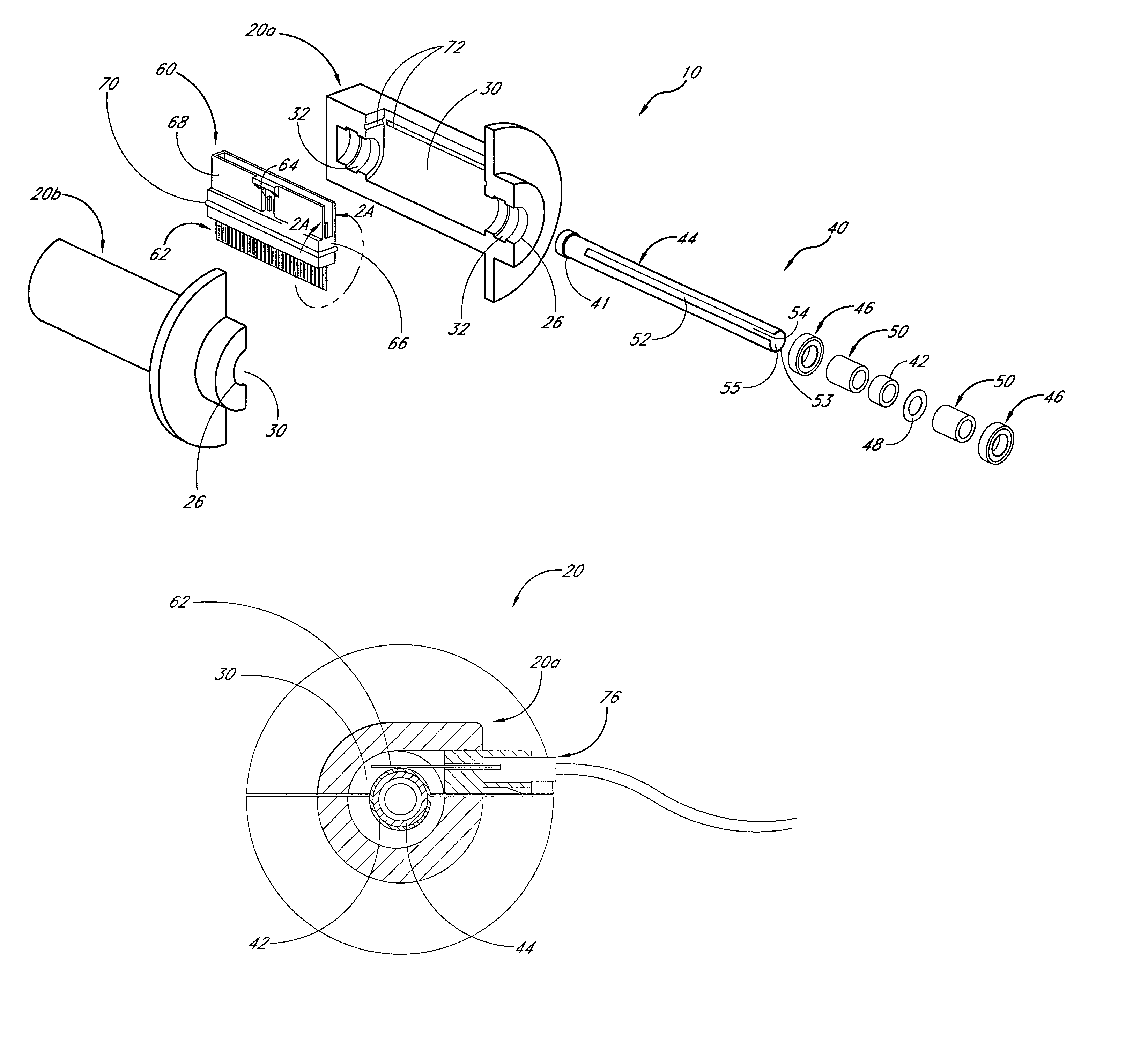
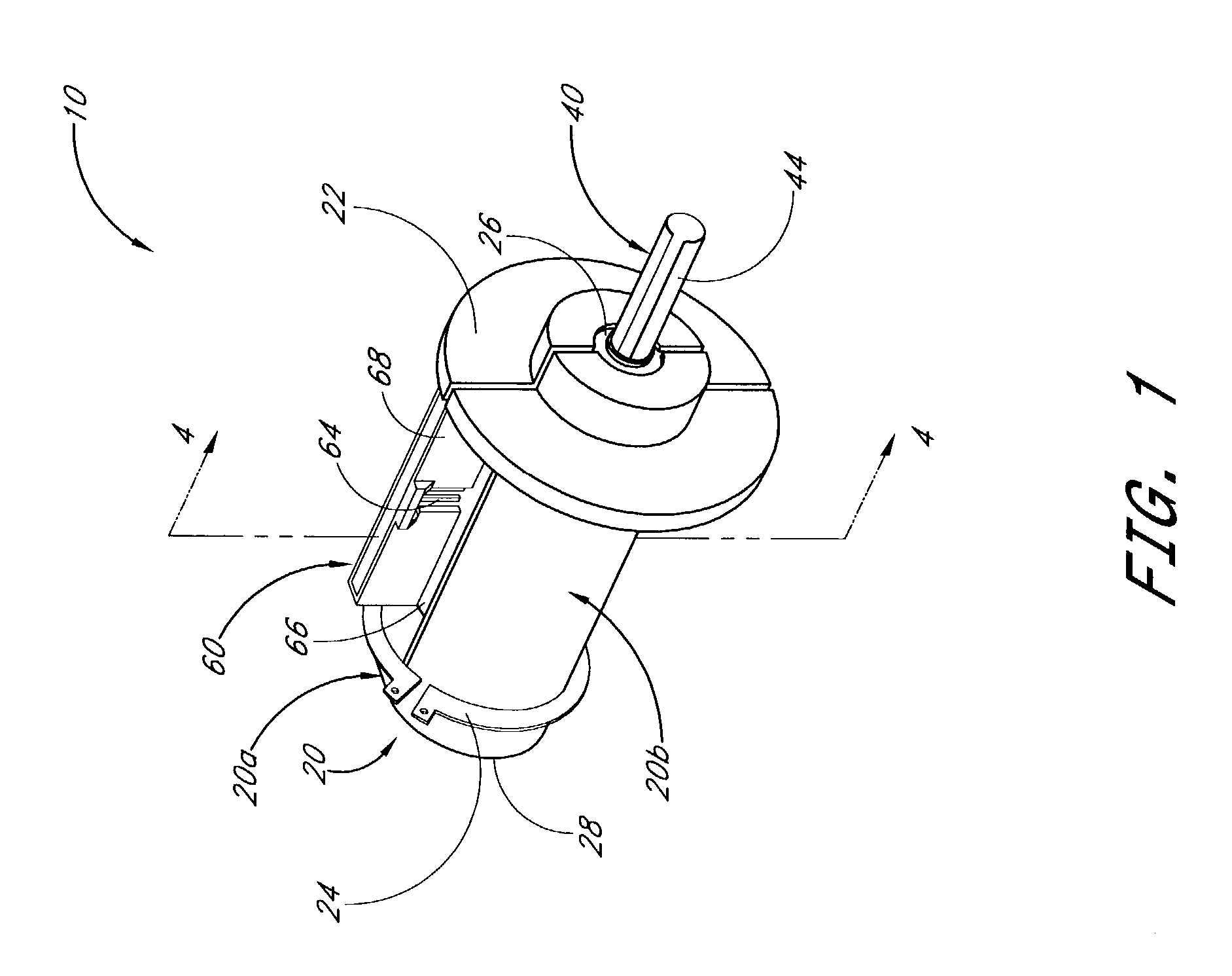
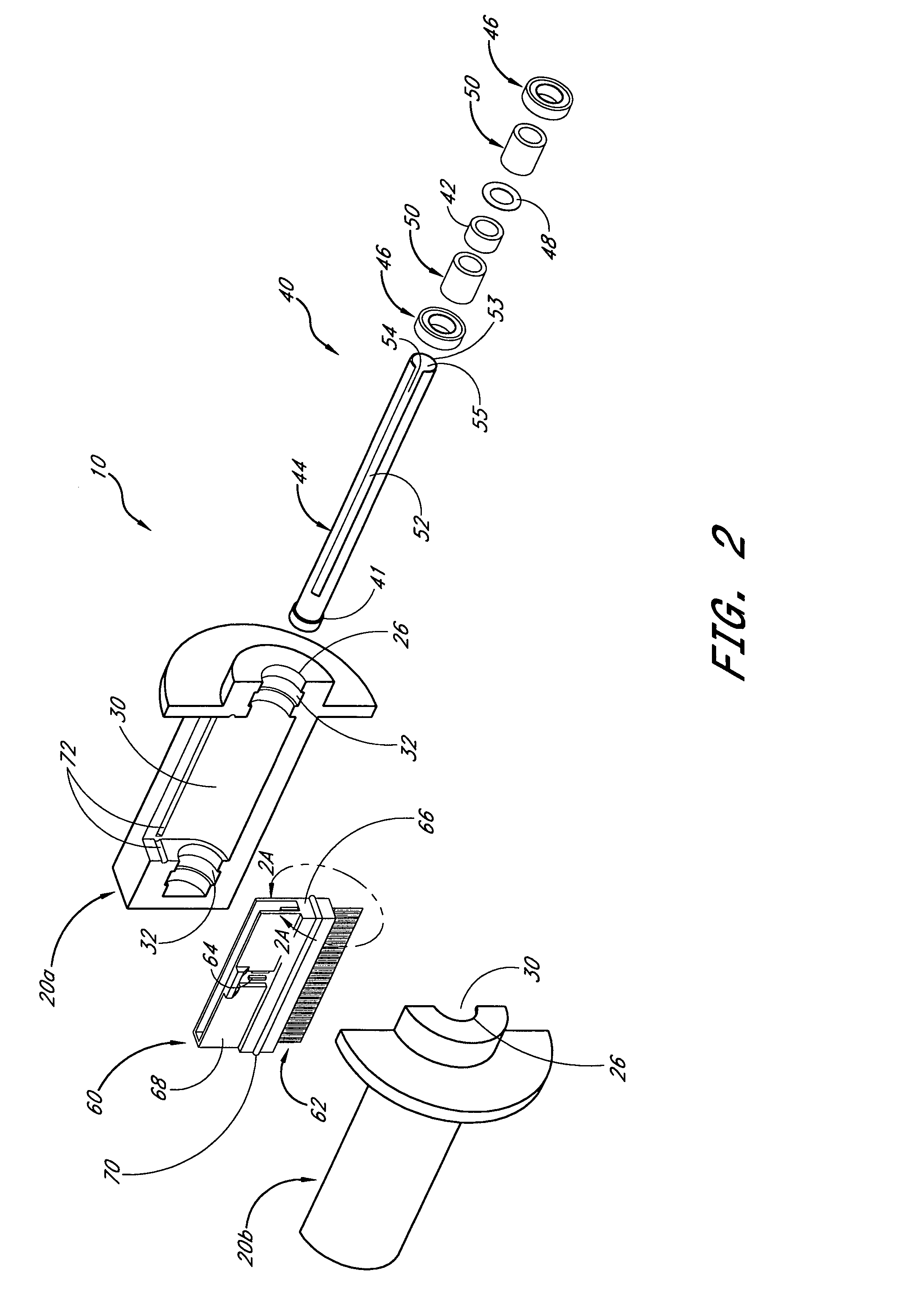
[0021]FIGS. 1–5 illustrate a slip ring assembly 10 having desirable features and advantages and usable in an electronic or electrical device (not shown) having a rotating component and a stationary component which are desirably maintained in electrical communication. The slip ring 10 generally includes a housing 20. The housing 20 typically includes a longitudinal channel for receiving a ring assembly 40. The ring assembly 40 typically includes a plurality of conductive rings 42 and insulating spacers 48 disposed on a central body 44 which is rotatable relative to the housing. Each ring 42 generally includes an electrical lead wire attached to an inner surface thereof which extends out an end of the central body 44. A brush assembly 60 having a plurality of brushes 62 and connector pins 64 extending from a brush holder 66 is removably received in the housing 20. See FIG. 5.

[0022]Typically, the housing 20 will be formed such that it may be mounted to a substantially stationary compon...


PUM


Abstract

A slip ring assembly for allowing electrical or electronic signal transfer between a stationary device and a rotating device includes a ring assembly and a brush assembly. The ring assembly comprises a plurality of assembled rings and spacers of selected widths positioned on a longitudinal tube having a slot and a hollow center. The tube may be provided with one or more bearings to allow the tube to be smoothly rotatable in a housing. A plurality of brushes unitarily formed with a plurality of connector pins are held by a brush holder which is removably received in the housing. The connector pins are configured to receive a standard male or female connector. The housing is typically incorporated into a body of a stationary device, and the tube may be attached to or incorporated into a rotating component of an electronic or electrical device.

Description

CROSS-REFERENCE TO PROVISIONAL APPLICATION[0001]This application claims the benefit of U.S. Provisional Patent Application Ser. No. 60 / 435,832, filed on Dec. 20, 2002, the entire contents of which is incorporated herein by reference.BACKGROUND[0002]1. Field of the Invention[0003]This invention relates to rotating electric connections, and specifically to a slip ring assembly with connector pins.[0004]2. Description of the Related Art[0005]Many electrical and electronic devices have rotating parts which must maintain electrical contact throughout rotation in order to transfer signals and / or power. Such devices typically require the use of slip rings which generally include one or more cylindrical contacts per circuit and one or more brushes configured to electrically contact the rings. As the rings rotate, the brushes ride and wear against the rings and eventually the brushes may have to be replaced. Additionally, if the rings are thinly plated, they may eventually become worn to a d...

Claims


Application Information

Patent Timeline
Patent Type & Authority Patents(United States)
IPC IPC(8): H01R39/00H01R39/24H01R39/36H01R43/12
CPCH01R39/24H01R43/12H01R39/36
Inventor ABOUCHAR, JOHN W.
Owner UNIT INDS
Why Eureka
Try Eureka