

Push pin device
a push pin and pin technology, applied in the field of push pin devices, can solve the problems of damage caused, damage that can result from the sharp tip, and the difficulty of removing the push pin and the article,
- Summary
- Abstract
- Description
- Claims
- Application Information
AI Technical Summary
Benefits of technology
Problems solved by technology
Method used
Image

Examples
Embodiment Construction
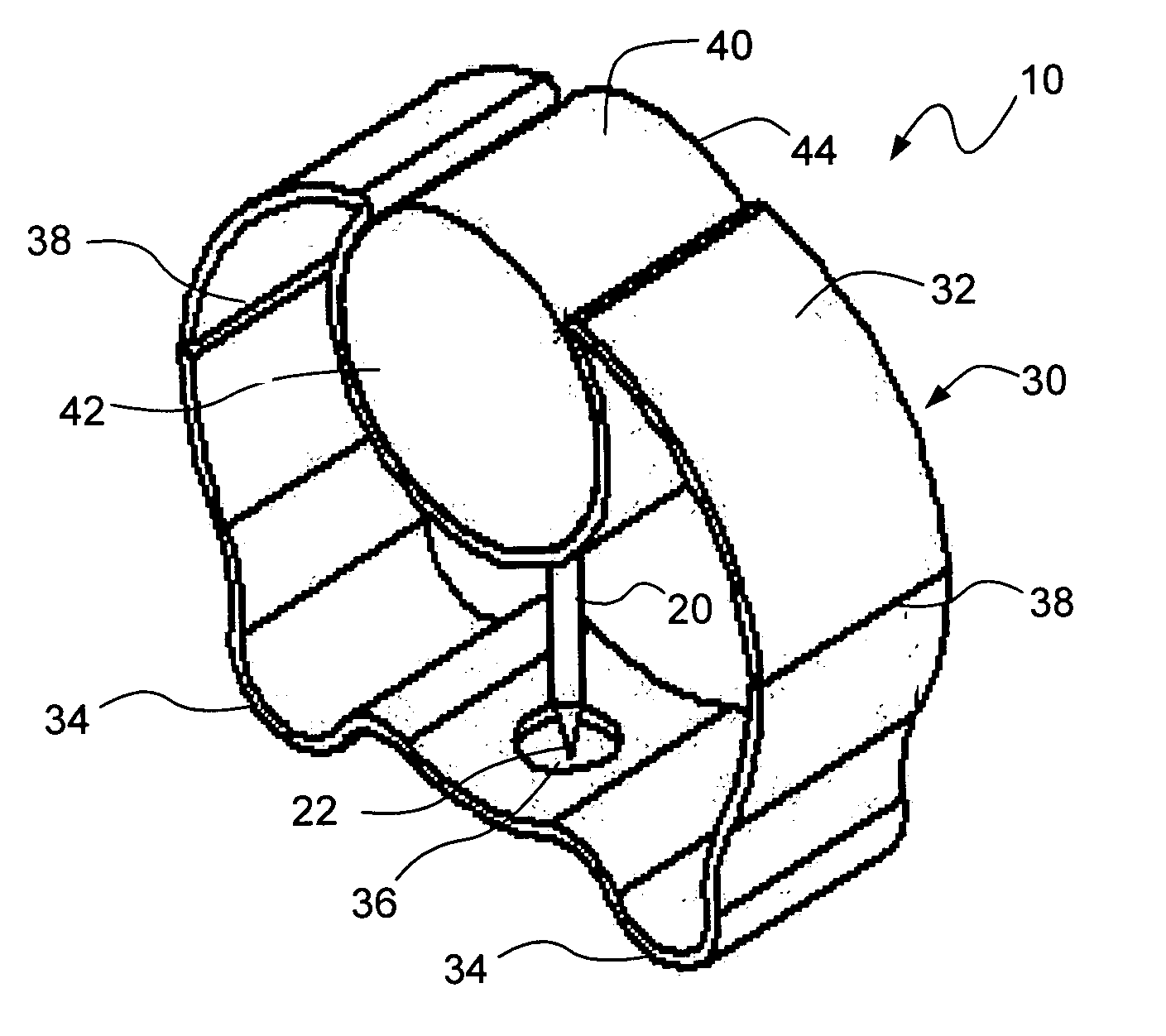
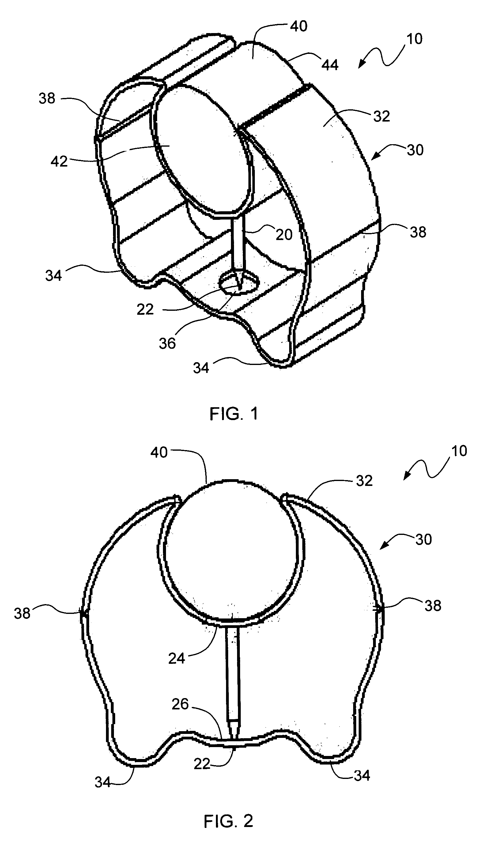
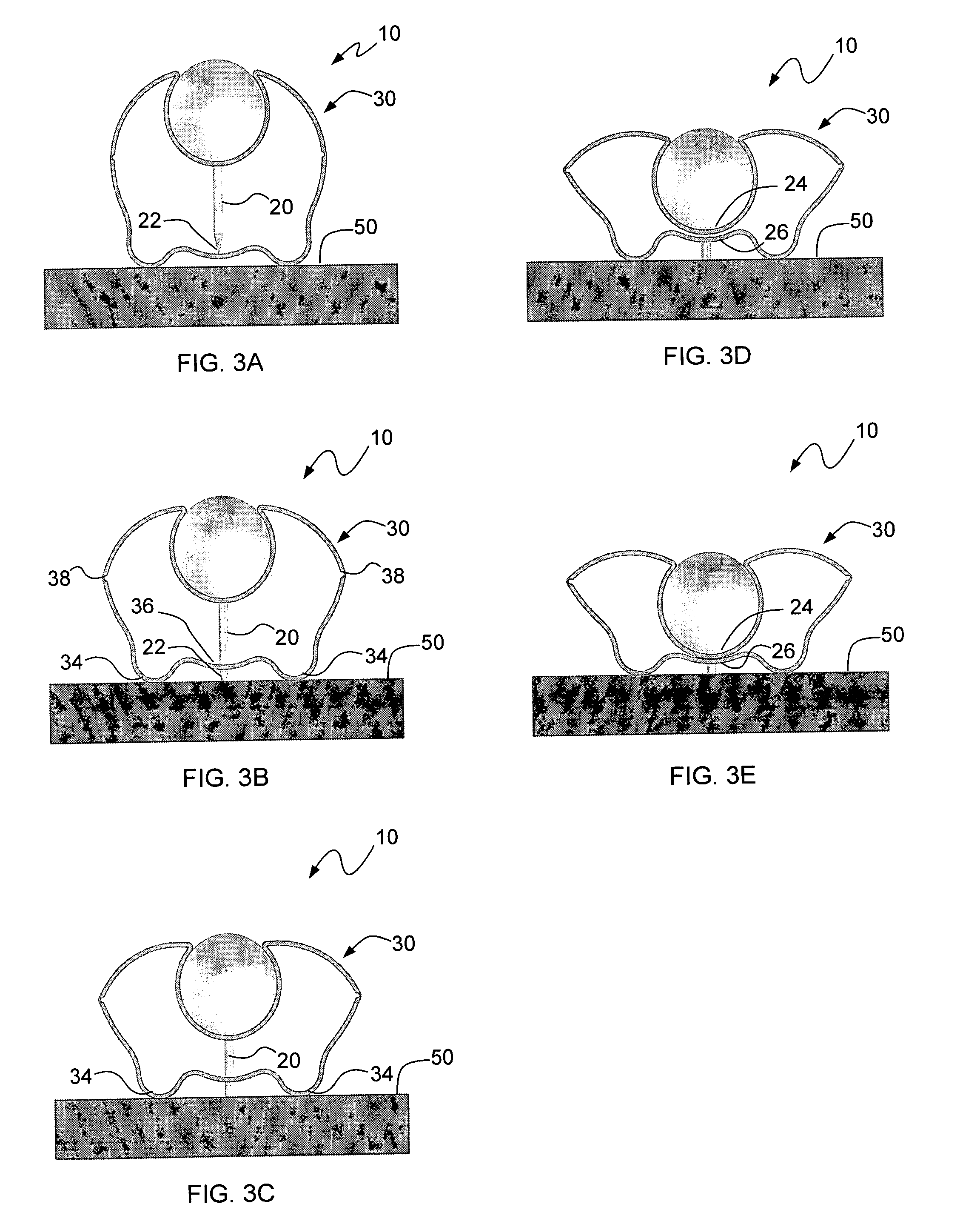
[0012]Referring to FIGS. 1 and 2, the exemplary push pin device 10 includes a pin 20 and a compressible article-engaging outer member 30 that at least partially surrounds the pin 20. The pin 10 is preferably formed of metal, but may be formed of other materials, such as plastic, for example, as long as such material allows the pin to be inserted into the pinnable surface. The pin 20 includes a tip 22 capable of piercing a pinnable surface such as FomCor, Homasote, or cork. Although a conical shaped tip 22 is shown in the exemplary embodiment, other tip configurations and shapes are contemplated.
[0013]The pin 20 generally extends from a first portion 24 of the outer member 30 toward a second portion 26 of the outer member 30. When the outer member 30 is in its non-deformed or non-compressed state, the pin 20 is retracted with respect to the outer member 30. When the outer member 30 is compressed, the pin 20 passes through the second portion 26 and is extended with respect to the oute...
PUM
 Abstract
Description
Claims
Application Information