Gas laser electrode, laser chamber employing the electrode, and gas laser device

Inactive Publication Date: 2006-02-28
GIGAPHOTON
View PDF15 Cites 0 Cited by
  • Summary
  • Abstract
  • Description
  • Claims
  • Application Information

AI Technical Summary

Benefits of technology

[0016]Thus, an object of the present invention is to provide a gas laser electrode in which stable laser output can be obtained by inhibiting the deterioration of the electrode (discharge characteristics).
[0017]Another object of the present invention is to provide a laser chamber employing the gas laser electrode in which stable laser output can be obtained by inhibiting the deterioration of the electrode (discharge characteristics).
[0018]A further object of the present invention is to provide a laser device equipped with the laser chamber employing the gas laser electrode in which stable laser output can be obtained by inhibiting the deterioration of the electrode (discharge characteristics).

Problems solved by technology

In this type of gas laser device, by the primary ignition electrodes being preionized with the preionization electrodes, laser gas is excited by the generation of electric discharge between the primary ignition electrodes, thereby causing laser oscillation.
Nevertheless, with the primary ignition electrodes described in aforementioned Documents 1˜3, laser output characteristics would suddenly change and the maintenance of the initial characteristics becomes difficult a result of the deformation of the anode surface (deformation into a convex-concave shape) due to the impact of electric discharge and the transformation of the electrode due to halogenation of electrode materials caused by the erosion with halogen gas at the anode surface.
In other words, it is not possible to obtain stable and desired laser output characteristics.
Thereby, problems would arise in that the electric discharge between the primary ignition electrodes becomes unstable, the output energy of the laser decreases and, as a result, desired laser output characteristics can not be obtained.
Moreover, in particular cases, the deteriorated anode (or the primary ignition electrode) must be replaced, resulting in inefficient workability.
Further, even if such deteriorated electrode is replaced with a new electrode, the aforementioned problems would similarly arise and, as a result, the cycle of replacing the electrode would occur frequently, resulting in increased maintenance costs.
Meanwhile, even with the primary ignition electrodes wherein a dielectric thin film is applied to the cathode surface thereof, as the discharging portion at which electricity is discharged between the anode and cathode is not coated, similar to the above, there is a problem in that stable laser output characteristics could not be obtained as a result of the deterioration of the anode (deformation of electrode) due to the impact of electric discharge, and the transformation of the electrode (anode) due to the halogenation (fluorination, for example) of the electrode materials.

Method used


Image

  • Gas laser electrode, laser chamber employing the electrode, and gas laser device
  • Gas laser electrode, laser chamber employing the electrode, and gas laser device
  • Gas laser electrode, laser chamber employing the electrode, and gas laser device

Examples


Embodiment Construction

[0053]The embodiments of the present invention are now described with reference to the attached drawings.

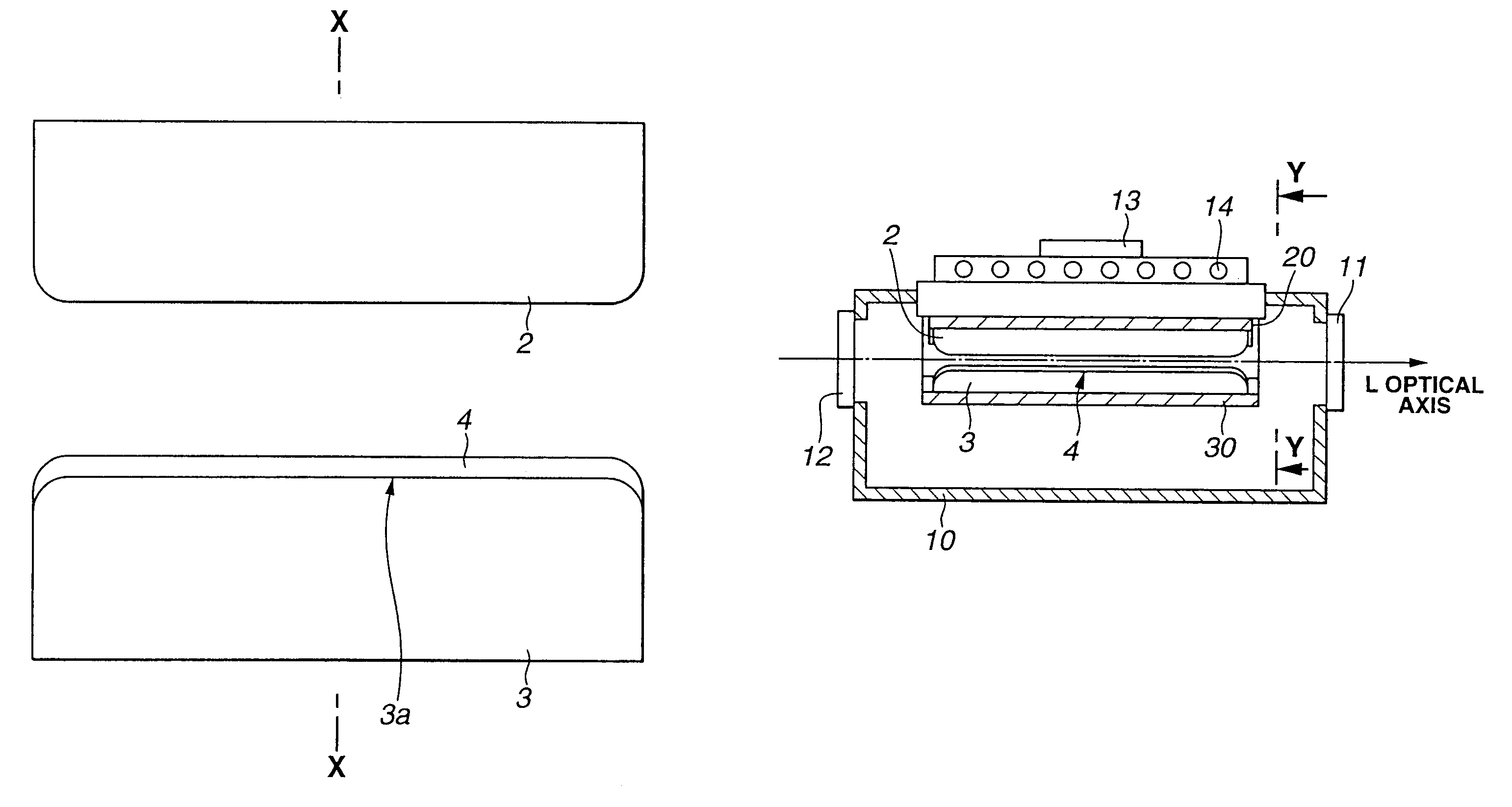
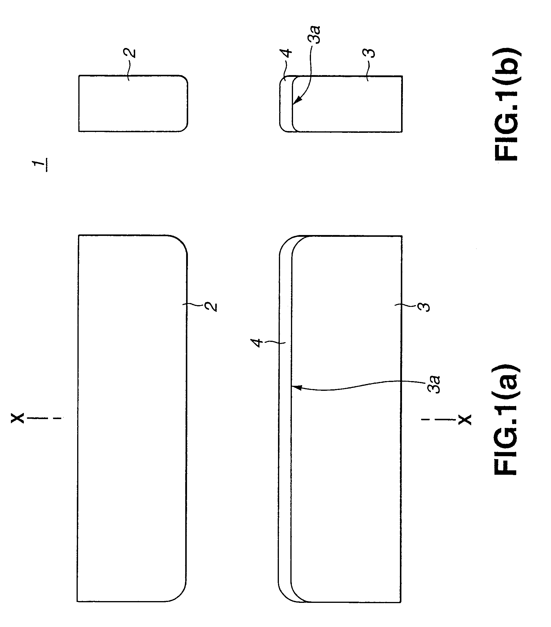
[0054]FIG. 1(a) is a cross section showing the principle section of the gas laser electrode according to the present embodiment, and FIG. 1(b) is a cross section showing the X—X line section in the gas laser electrode shown in FIG. 1(a).

[0055]The gas laser electrode 1 is formed of a cathode 2 and anode 3 as depicted in FIGS. 1(a) and 1(b), and these electrodes are arranged inside the laser chamber in a gas laser device, such as an excimer laser device, for example, so as to face each other while sandwiching the optical axis of the laser. The arrangement of the respective electrodes 2, 3 inside the laser chamber may be arranged in a relationship similar to those conducted conventionally and, here, such description is thereby omitted. Further, the gas laser device employing this gas laser electrode 1 will be explained later.

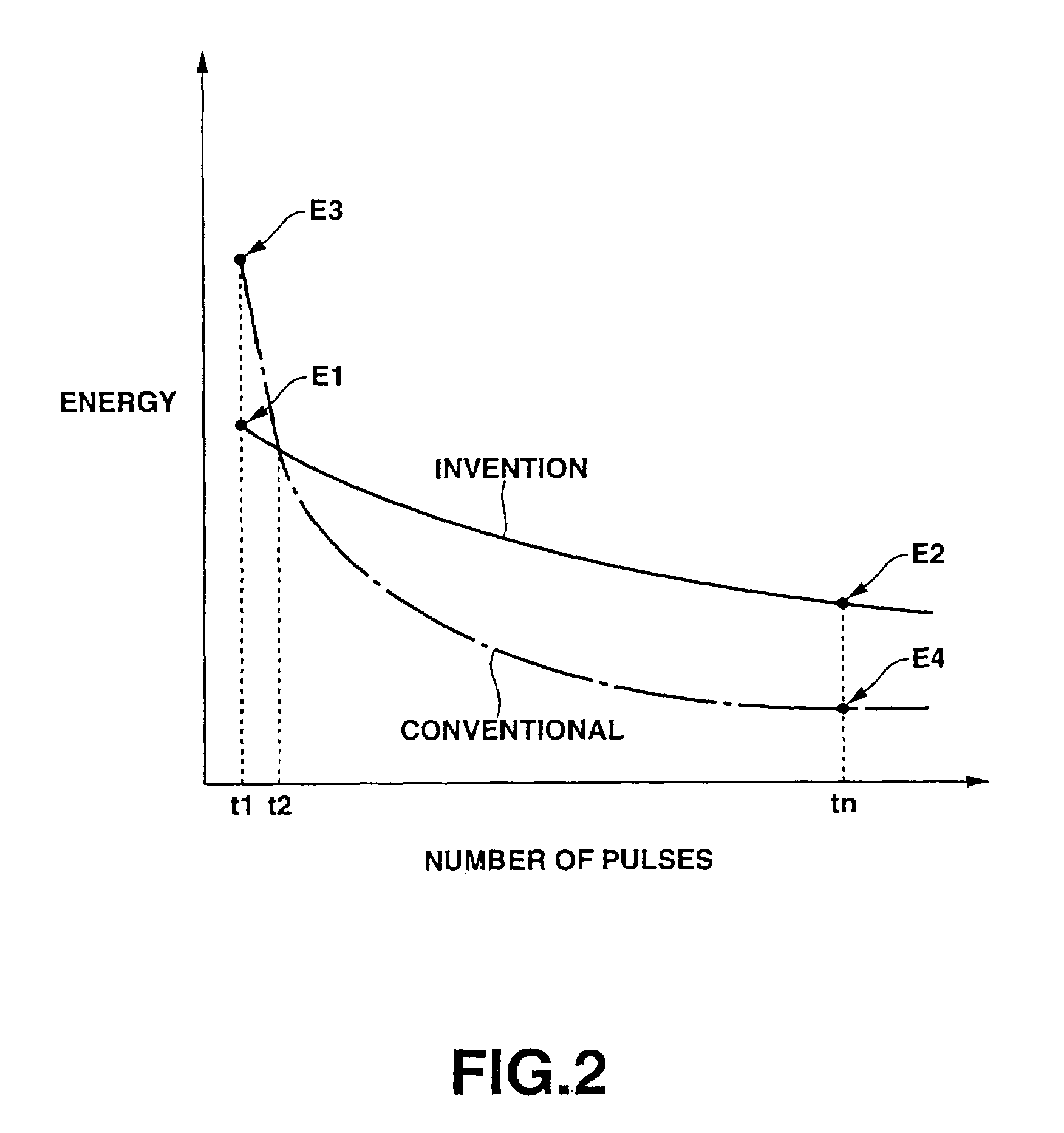
[0056]Meanwhile, filled inside the aforementioned laser ch...


PUM


Abstract

Provided is a gas laser electrode in which a stable laser output can be obtained by inhibiting the deterioration of the electrode (discharge characteristics). In an anode 3, a dielectric material 4 is applied on the surface of a discharging portion 3a in order to inhibit the deterioration of the electrode. Used as a dielectric material 4 may be, for example, fluorides such as calcium fluoride and strontium fluoride. Further, the dielectric material 4 is of a thickness (in a range of 0.005 mm˜1.5 mm, preferably 0.1 mm˜1 mm, for example) sufficient to prevent the erosion of halogen gas in the discharging portion 3a of the anode 3 and to secure a conductivity thereof, whereby it is enabled to form mono-fluoride evenly in extreme precision.

Description

BACKGROUND OF THE INVENTION[0001]1. Field of the Invention[0002]The present invention relates to a gas laser electrode for exciting laser gas, a laser chamber employing such electrode, and a gas laser device.[0003]2. Description of the Related Art[0004]In a laser chamber of a typical gas laser device such as an excimer device, provided are primary ignition electrodes facing each other and arranged so as to sandwich an optical axis of a laser for exciting the laser gas filled inside the laser chamber and causing laser oscillation, and preionization electrodes for preionizing the space between the primary ignition electrodes so as to make the discharge of electricity between such electrodes easier. As the laser gas, for example, used may be a mixed gas of noble gas and halogen gas.[0005]In this type of gas laser device, by the primary ignition electrodes being preionized with the preionization electrodes, laser gas is excited by the generation of electric discharge between the primary...

Claims


Application Information

Patent Timeline
IPC IPC(8): H01S3/22H01S3/038H01S3/225
CPCH01S3/038H01S3/225
Inventor HORI, TSUKASAFUJIMOTO, JUNICHIYABU, TAKAYUKI
Owner GIGAPHOTON
Why Eureka
Try Eureka