Cable hanger

Inactive Publication Date: 2006-03-07
COMMSCOPE TECH LLC
View PDF52 Cites 68 Cited by
  • Summary
  • Abstract
  • Description
  • Claims
  • Application Information

AI Technical Summary

Problems solved by technology

Generally, antenna poles and towers are crowded due to the multiplicity of cables required for signal-carrying.
Conventional cable hangers configured to hold relatively small-diameter braided and corrugated cables suffer from significant deficiencies and shortcomings.
In addition, specifically-dimensioned cable hangers may be unable to accommodate variation

Method used


Image

  • Cable hanger
  • Cable hanger
  • Cable hanger

Examples


Embodiment Construction

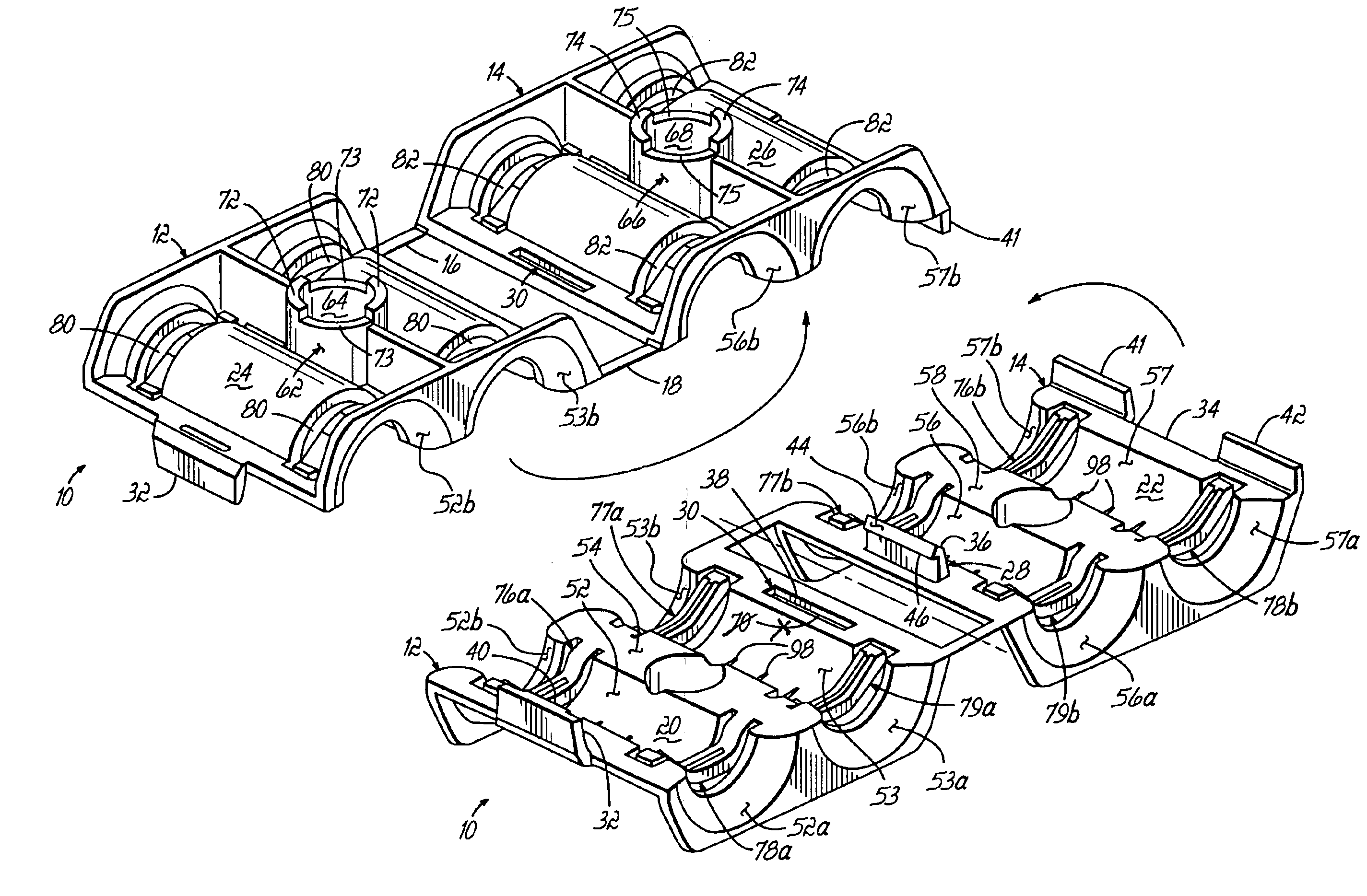
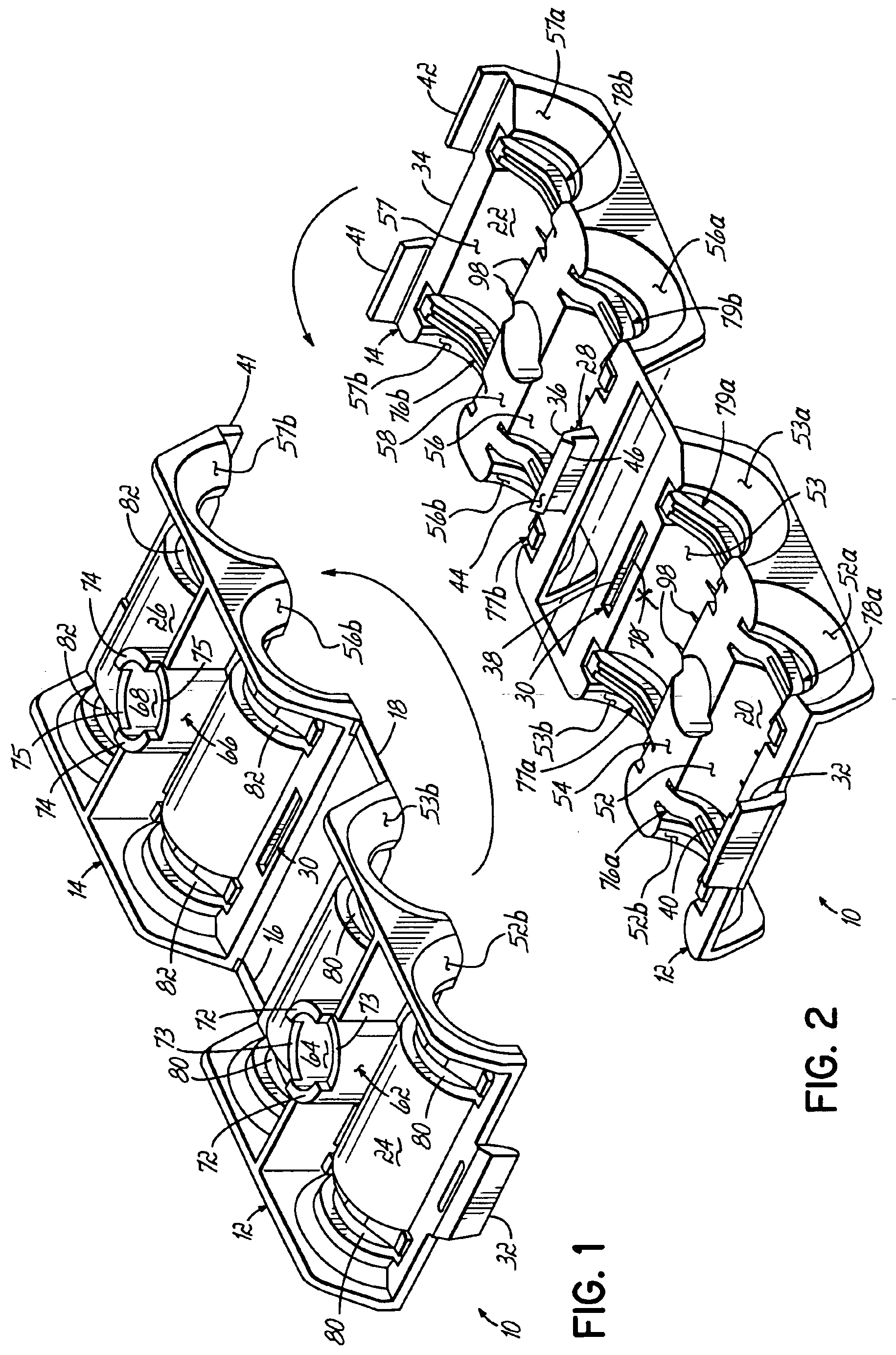
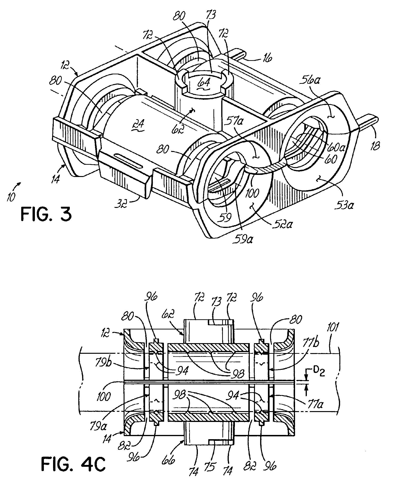
[0014]The invention is directed to cable hangers configured for securing a plurality of, for example, two cables within a range of cable diameters and, in doing so, grip each cable with a relatively uniform gripping force about its circumference. Although the invention will be described next in connection with certain embodiments, it will be understood that the invention is not limited to those particular embodiments. On the contrary, the description of the invention is intended to cover all alternatives, modifications, and equivalent arrangements as may be included within the spirit and scope of the invention as defined by the appended claims.

[0015]With reference to FIGS. 1 and 2, a cable hanger 10 of the invention includes a front shell half 12 and a rear shell half 14 hingeably joined together by a spaced-apart pair of living hinge couplings 16, 18. The shell halves 12, 14 are folded or closed one onto the other so as to create an enclosing or encasing structure. When folded, res...


PUM


Abstract

A cable hanger for securing multiple cables to support structures including antenna towers and poles. The cable hanger has a hingeably-coupled pair of shell halves with recesses that, when folded, establish a pair of cable passageways. Gripping arms provided on each of the shell halves project into a corresponding one of the cable passageways for gripping a cable positioned therein. Pairs of gripping arms located on opposite shell halves have a confronting relationship for gripping the cable on diametrically opposite side surfaces.

Description

FIELD OF THE INVENTION[0001]This invention relates generally to devices for hanging cables and, in particular, to hangers for securing cables to structures including antenna poles and towers.BACKGROUND OF THE INVENTION[0002]Cable hangers are commonly used to secure cables to structural members of antenna poles and towers. Cables carry signals from ground-level equipment to sets of antennas attached at elevated positions on an antenna tower. Generally, each cable is attached to the antenna tower by a set of cable hangers mounted at periodically-spaced attachment points along its height. After the cable hangers have been attached to the antenna tower, the cable is strung upwardly and engaged with each of the cable hangers.[0003]Generally, antenna poles and towers are crowded due to the multiplicity of cables required for signal-carrying. To conserve tower space, it is desirable for each set of cable hangers to have a capacity to route more than a single cable up the antenna tower. Cer...

Claims


Application Information

Patent Timeline
IPC IPC(8): F16L3/22H02G7/05
CPCH02G7/053H02G3/32
Inventor GOODWIN, KEVINCOX, ALBERT R.
Owner COMMSCOPE TECH LLC
Why Eureka
Try Eureka