Progressive tire tread wear indicator

a tire tread and wear indicator technology, applied in the direction of tires, vehicle components, non-skid devices, etc., can solve the problem of difficult to determine the level of wear

Inactive Publication Date: 2006-03-14
THE GOODYEAR TIRE & RUBBER CO
View PDF13 Cites 38 Cited by
  • Summary
  • Abstract
  • Description
  • Claims
  • Application Information

AI Technical Summary

Benefits of technology

[0004]The invention is directed to a tire having wear indicators that assist the operator in determining the level of wear of a tire tread.

Problems solved by technology

The practical problem with the colored indicators of the type mentioned is that there is way for the operator to determine the level of wear until the tire is worn.
When the tire employs the tie-bar type wear indicator, since the wear indicator is the same color as the remaining part of the tread, it can be difficult to determine the level of wear.

Method used


Image

  • Progressive tire tread wear indicator
  • Progressive tire tread wear indicator
  • Progressive tire tread wear indicator

Examples


Embodiment Construction

[0031]The following language is of the best presently contemplated mode or modes of carrying out the invention. This description is made for the purpose of illustrating the general principals of the invention and should not be taken in a limiting sense. The scope of the invention is best determined by reference to the appended claims.

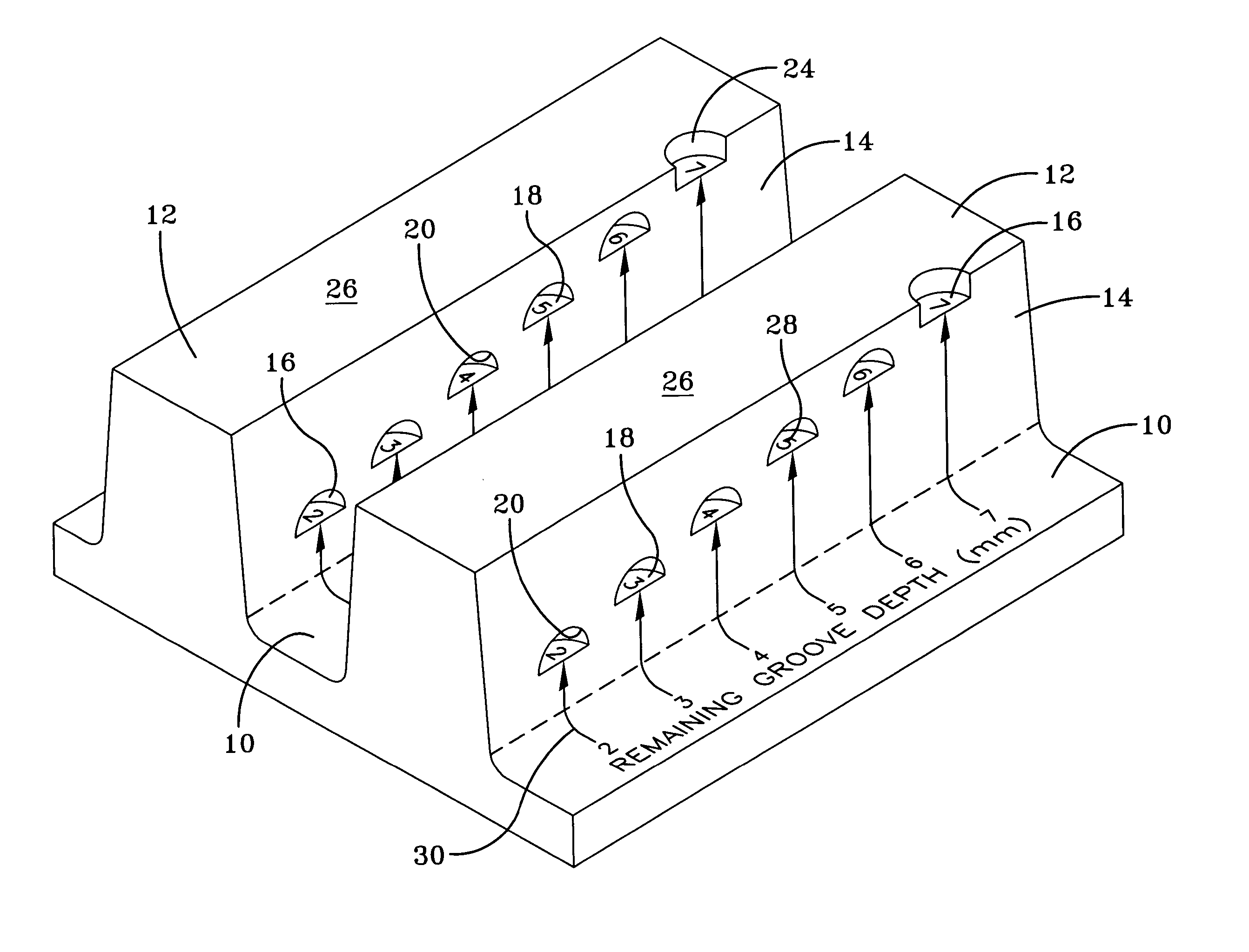
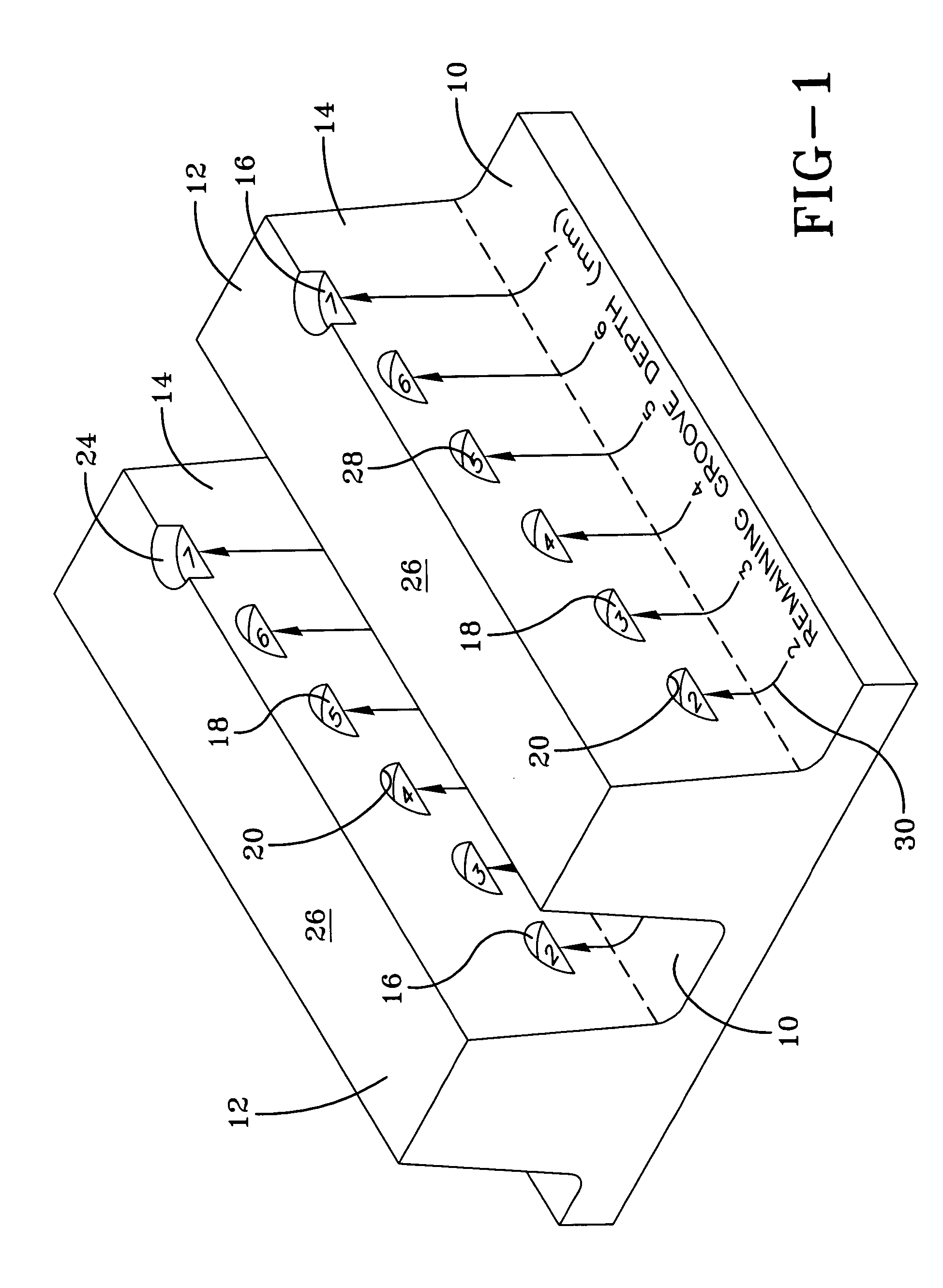
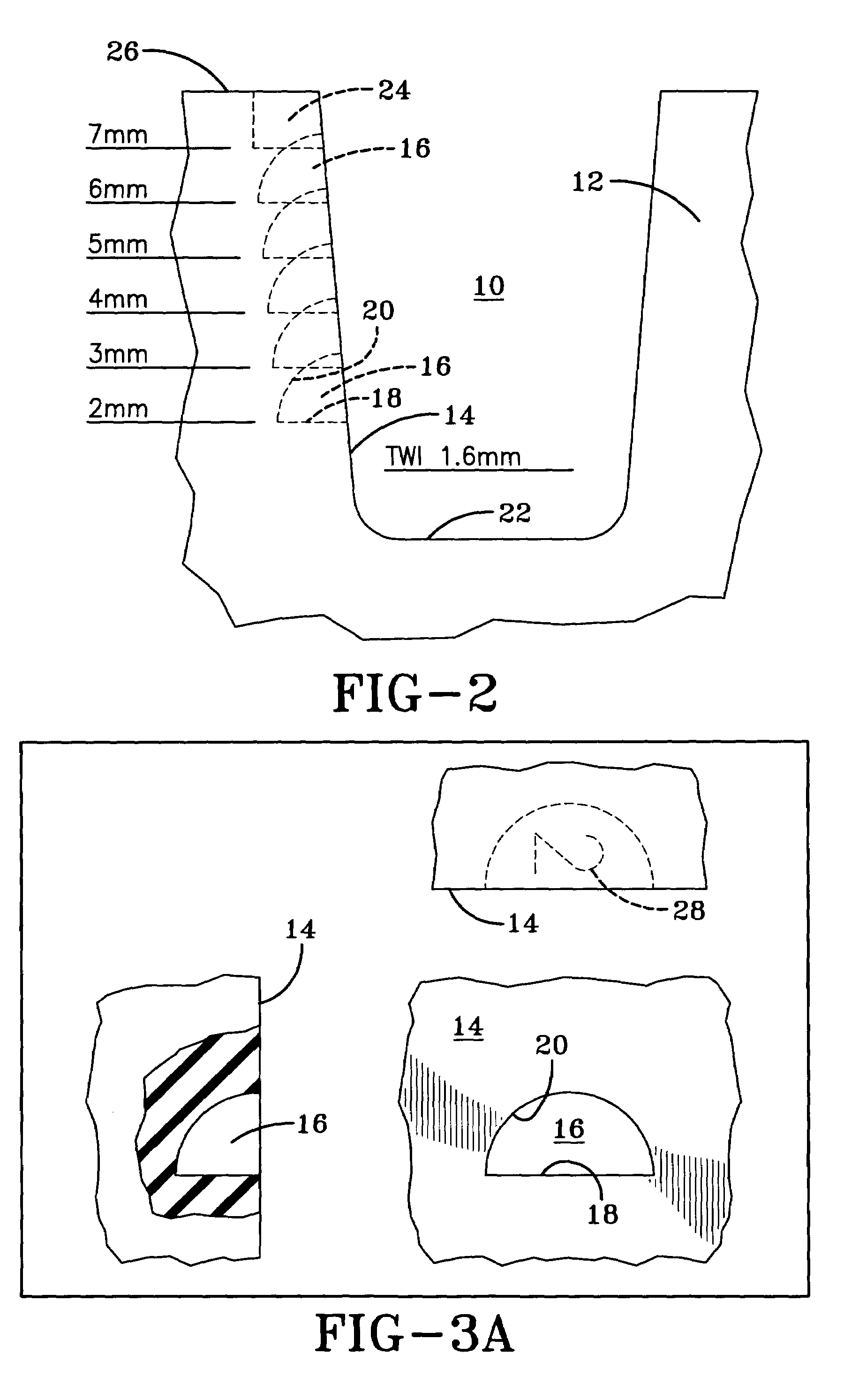
[0032]A portion of a tire tread is illustrated in FIG. 1. The tread is characterized by at least one circumferentially extending groove 10 and adjacent ribs 12. Each rib 12 has at least one radially extending sidewall 14 that faces the circumferential groove 10. Those skilled in the art will appreciate that the tire tread may have more than one circumferential groove 10 and multiple continuous or non-continuous ribs 12.

[0033]Located in the rib sidewall 14 is at least one tread wear indicating cavern 16. The cavern 16 is defined by a base 18 that is a radially inner surface parallel to the outer surface of the rib 12 and a ceiling 20 that is a radially o...


PUM


Abstract

A tire tread has at least one cavern formed in the sidewall of the traction elements of the tire. The cavern has a base with information therein to indicate the state of wear of the tire and a ceiling that is progressively worn away as the tread wears. Multiple caverns may be formed in the traction elements. If arranged in a series at progressively increasing or decreasing radial heights, the remaining tread life is communicated to an operator. If the caverns are located in different locations of the tread, relative wear patterns of the tire can also be indicated.

Description

FIELD OF THE INVENTION[0001]The present invention is directed to a tire tread including wear indicators.BACKGROUND OF THE INVENTION[0002]The use of treadwear indicators is not new and the use of treadwear indicators is mandated by law in many countries. A variety of such indicators are known. Once such type employs colored means, such as colored rubber or colored fibers, below the tread for a visual indicator of wear. Other types use tie-bar type elements in the tread grooves. When required by law, the upper surface of the tread wear indicator must be located at a height of 1.6 mm from the base of the groove in which the wear indicator is located.[0003]The practical problem with the colored indicators of the type mentioned is that there is way for the operator to determine the level of wear until the tire is worn. When the tire employs the tie-bar type wear indicator, since the wear indicator is the same color as the remaining part of the tread, it can be difficult to determine the ...

Claims


Application Information

Patent Timeline
Patent Type & Authority Patents(United States)
IPC IPC(8): B60C11/00B60C11/24B60C11/13
CPCB60C11/032B60C11/24Y10T152/10027B60C2011/133
Inventor HEINEN, RICHARD
Owner THE GOODYEAR TIRE & RUBBER CO
Why Eureka
Try Eureka