
Engine tilting tool

a tool and engine technology, applied in the direction of wrenches, screwdrivers, wire tools, etc., can solve the problems of difficult service of engines, difficult access to engines, etc., and achieve the effect of being cheap

Inactive Publication Date: 2006-03-21
LISLE CORPORATION
View PDF4 Cites 2 Cited by
  • Summary
  • Abstract
  • Description
  • Claims
  • Application Information

AI Technical Summary

Benefits of technology

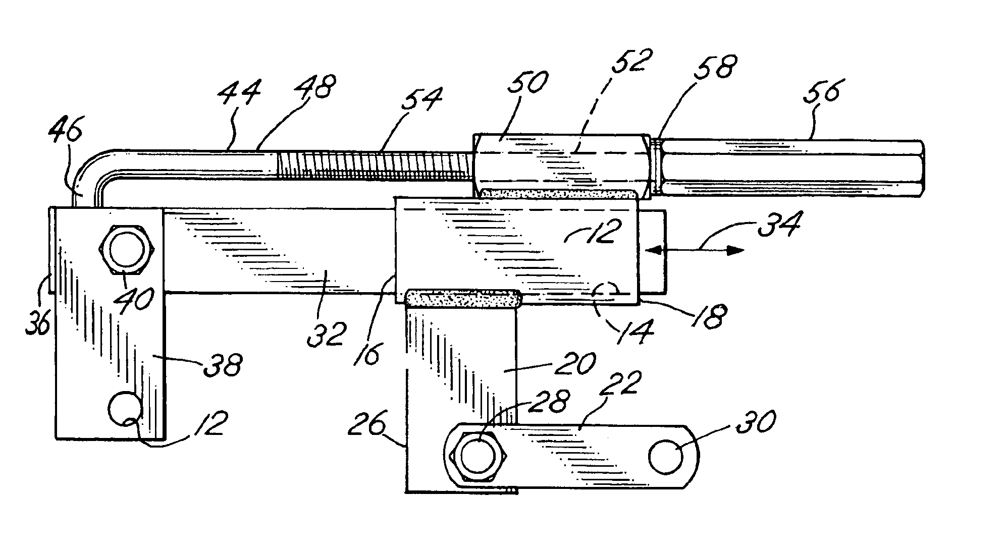
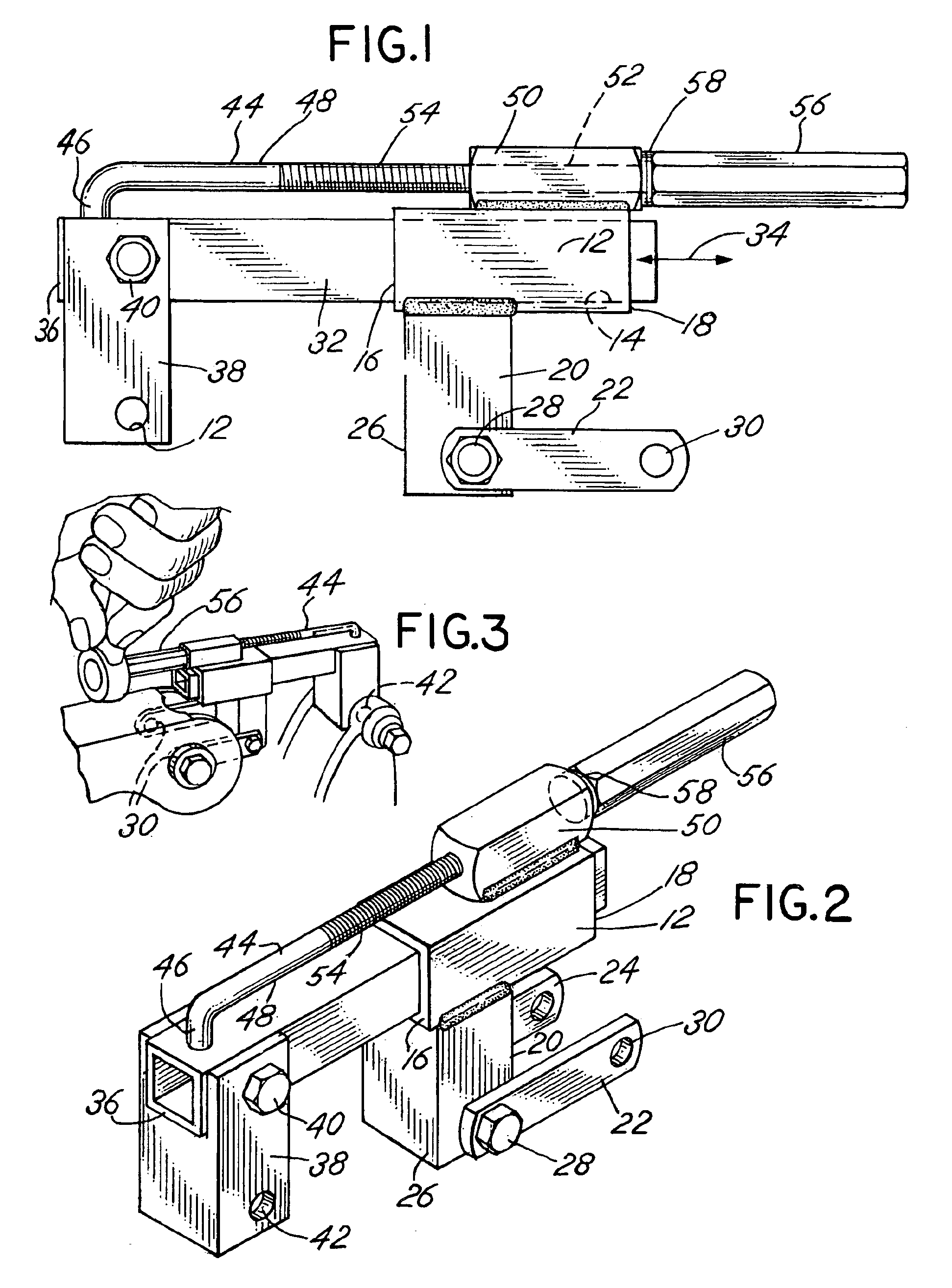
[0006]Thus, in order to tilt an engine about mounting pins or bolts in the engine compartment, the telescoping tube extension member is attached to the engine at the connection point of the “dog bone” strut and the tubular bracket depending attachment leg of the tool is attached to the engine compartment at the “dog bone” strut connection point. Then by slidably adjusting the position of the telescoping tube within the tubular bracket member, the engine may be efficiently and effectively tilted and maintained in an adjusted, tilted position.
[0008]Thus it is an object of the invention to provide an inexpensive, yet exceedingly rugged and strong tool to replace the “dog bone” struts of a General Motors type transversely mounted engine to effect tilting of the engine.

Problems solved by technology

Such engines, particularly in General Motors vehicles, may be difficult to service inasmuch as the component parts, such as spark plugs, the oxygen sensor, ignition coil and the like, are positioned in a manner which makes access thereto somewhat difficult.

Method used


Image

  • Engine tilting tool
  • Engine tilting tool

Examples


Embodiment Construction

[0016]As shown in the figures, the tool of the invention includes a tubular bracket member 12 which is comprised of a generally square cross section tubular member having a throughpassage 14 extending from a forward end 16 through a rear or back side or back end 18. A depending attachment leg 20 extends vertically downwardly from the tubular bracket member 12 and is welded thereto. The depending attachment leg 20 further includes a first linkage bar or a link 22 and a second, generally parallel, substantially identical linkage bar or link 24. Linkage bars 22 and 24 are pivotally attached to the lower end 26 of the attached leg 20 by means of a pivot pin or bolt 28. The links 22 and 24 each include a throughpassage 30 at their outer free end, which enables attachment of the links 22 and 24 to an attachment bracket connection point in the engine compartment for a “dog bone” strut.

[0017]A telescoping tube 32 is slidably and telescopically positioned within the tubular bracket 12 for sl...


PUM


Abstract

An engine tilting tool used to tilt transversely mounted General Motors engines includes a tubular bracket member which receives a telescoping tubular member that is driven telescopically by means of a drive rod mounted on the bracket member. The bracket member is attached to the vehicle engine compartment in place of one end of the “dog bone” strut engine support and the telescoping tubular member is attached to the engine in place of the opposite end of the strut engine support. A nut is used to adjust the position of the telescoping tube relative to the tubular bracket member to thereby effect tilting of the engine.

Description

BACKGROUND OF THE INVENTION[0001]In principal aspect of the present invention relates to a tool used to support and tilt the engine of a motor vehicle in the engine compartment of the vehicle so that the component parts of the engine, such as spark plugs and the like, will be more accessible for purposes of service or replacement.[0002]Front wheel drive vehicles typically include an engine which is mounted transverse to the longitudinal axis of the vehicle. Such engines, particularly in General Motors vehicles, may be difficult to service inasmuch as the component parts, such as spark plugs, the oxygen sensor, ignition coil and the like, are positioned in a manner which makes access thereto somewhat difficult. In order to improve accessibility, the engine struts, which are often referred to as “dog bone” struts, may be detached and replaced by a mechanism which is operated to tilt the engine a limited amount while in the engine compartment. Such tilting exposes and makes more readil...

Claims


Application Information

Patent Timeline
Patent Type & Authority Patents(United States)
IPC IPC(8): B25B11/00B25B27/00
CPCB25B27/0035
Inventor WILLIAMS, DANNY
Owner LISLE CORPORATION
Learn More