Removable auxiliary handle for tools

a technology of auxiliary handles and tools, applied in the field of auxiliary handles, can solve the problems of low ergonomic posture of users, back pain and injuries caused by these, and cannot be adapted to a wide variety of shaft diameters, and is less interesting on an economic asp

Active Publication Date: 2006-03-21
BOSA ALAIN
View PDF41 Cites 24 Cited by
  • Summary
  • Abstract
  • Description
  • Claims
  • Application Information

AI Technical Summary

Problems solved by technology

One of the major drawbacks associated with this conventional tool handle configuration is the low ergonomic posture of the user and back pain and injuries caused therefrom.
Those designed to be removably attached to a garden tool, as provided in U.S. Pat. No. 6,553,627, are unfortunately not designed to be adapted to a wide variety of shaft diameters.
Therefore, all solutions proposed in the prior art require that a user be provided with multiple auxiliary handles to be adapted on a range of garden tools, which is less interesting on an economical aspect.

Method used


Image

  • Removable auxiliary handle for tools
  • Removable auxiliary handle for tools
  • Removable auxiliary handle for tools

Examples


Embodiment Construction

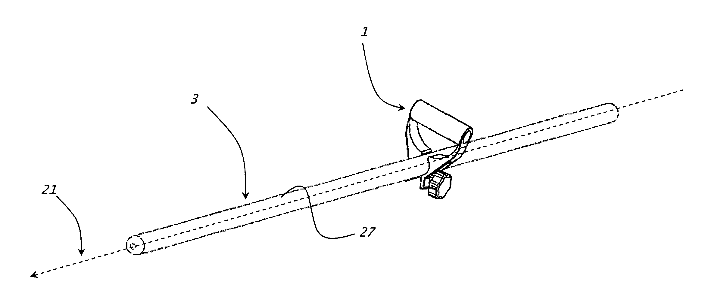
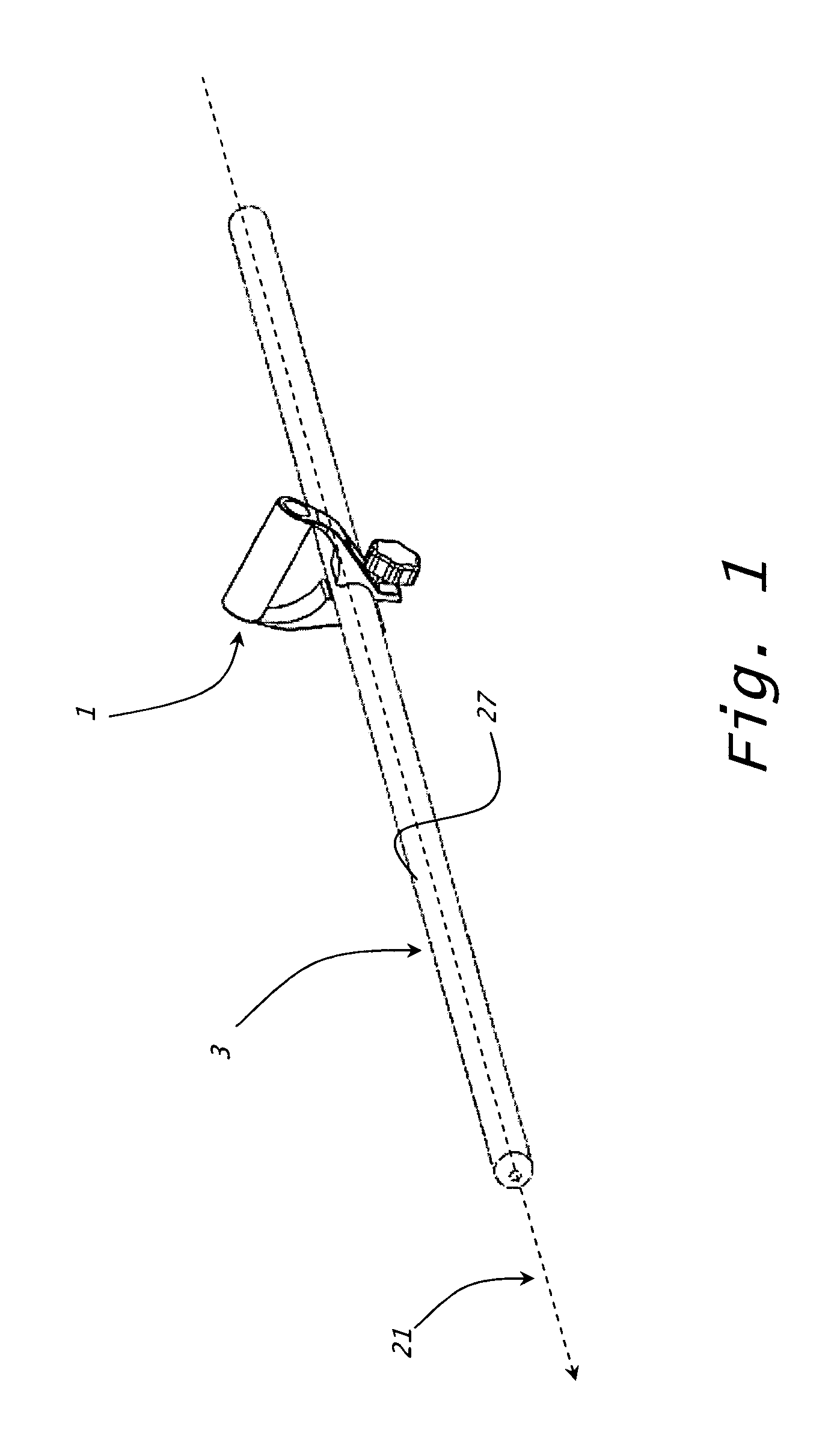
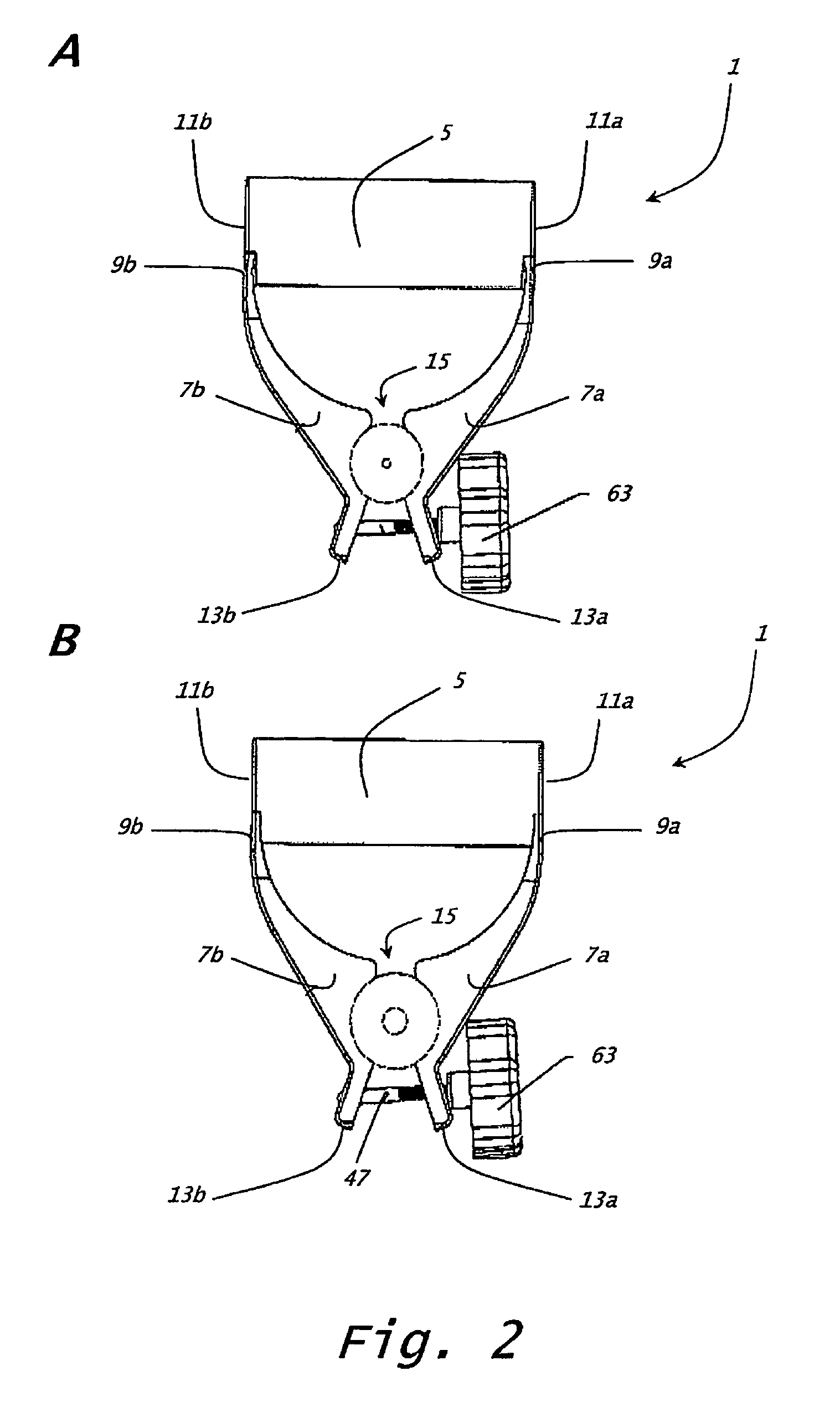
[0018]Referring to the drawings, more particularly FIGS. 1 to 4, an auxiliary handle 1 for use on an elongated rod-shaped handle 3 of a garden tool, such as a plow, a rake or a fork, will be described. Auxiliary handle 1 generally has a D-shape and comprises a grip 5 designed to accommodate the hand of a user and two opposed and generally symmetrical clamping members 7a,7b which are solely connected to each other via the grip 5.

[0019]Each clamping member 7a, 7b is perpendicularly attached by its upper extremity 9a, 9b to one side extremity 11a, 11b of grip 5. Extremities 13a,13b of clamping members 7a,7b distal from grip 5 converge while remaining physically free one from the other so that grip 5 and both clamping members 7a,7b define an open loop comprising an opening 15. Clamping members 7a,7b and grip 5 are preferably made from a resilient material and more preferably from a plastic material in a manner such that the width of opening 15 can be modified to accommodate elongated ha...


PUM


Abstract

An auxiliary handle for use on an elongated rod-shaped handle of a tool includes an open loop member with a pair of opposed clamping arms connected to each other solely at a first end thereof via a gripping portion. The clamping arms have free distal end portions defining therebetween an opening adapted to receive the elongated rod-shaped handle. The clamping arms are displaceable about the gripping portion between a first position for accommodating rod-shaped handles of different cross-sectional dimensions and a second position wherein the clamping arms are resiliently depressed one towards the other for clamping onto the rod-shaped handle of the tool. The auxiliary handle also includes an actuator adapted to be connected to the clamping arms for controlling their movement between the first and second positions.

Description

BACKGROUND OF THE INVENTION[0001](a) Field of the Invention[0002]The present invention generally relates to an auxiliary handle for use on an elongated rod-shaped handle of a tool.[0003](b) Description of Prior Art[0004]The use of handles is known from the prior art since many decades to grab tools such as garden tools. Among the existing handles designed to manipulate garden tools, the most commonly known handles comprise an elongated rod portion having the general structure of a shaft at the lower end of which the tool head is grafted. A grip is typically provided at the upper end of the elongated rod handle to facilitate manipulation of the tool. This configuration allows a user to grab the tool by placing one hand on the shaft portion near the head of the tool and the other hand on the other end of the elongated rod handle or on the grip affixed thereto.[0005]One of the major drawbacks associated with this conventional tool handle configuration is the low ergonomic posture of th...

Claims


Application Information

Patent Timeline
Patent Type & Authority Patents(United States)
IPC IPC(8): A01B1/22A01B1/02B25G1/00B25G1/06
CPCA01B1/026B25G1/00B25G1/06Y10T16/4713Y10T16/498
Inventor BOSA, ALAIN
Owner BOSA ALAIN
Why Eureka
Try Eureka