Monitoring of fuel on a grate fired boiler

a technology of grate fired boiler and monitoring fuel, which is applied in the direction of solid fuel combustion, combustion types, lighting and heating apparatus, etc., can solve the problems of reducing the efficiency of the burning process, excessive production or insufficient production of steam output from the boiler, and the rate of incoming fuel not being able to provide a clear indication

Active Publication Date: 2006-03-28
INT PAPER CO
View PDF6 Cites 16 Cited by
  • Summary
  • Abstract
  • Description
  • Claims
  • Application Information

AI Technical Summary

Benefits of technology

[0008]In one embodiment, the weight of the fuel load at the fuel-receiving end of the grate and at the discharge end of the grate, at least, is sensed. Further, weight sensors preferably are located at spaced apart locations across the width of the grate, at locations intermediate the opposite ends of the top run of the grate. Through this means, there is obtainable a two-dimension map of the distribution of the fuel over substantially the entire fuel-supporting surface of the grate. Employing multiple fuel infeed sources, along with the two-dimensional map, permits the operator or automatic controller to select which particular one or ones of the multiple infeed sources should be selectively adjusted with respect to its contribution to the infeed of fuel onto the grate.

Problems solved by technology

It will be recognized that each of these methods of monitoring the progression of the burning of the fuel and the rate on incoming fuel to feed the combustion do not have the ability to provide a clear indication of the amount of material residing on the grate at any given time or over a period of time.
Burning of fuel on a grate fired boiler is often limited due to the risk of excessive piling on of the fuel on the grate with an accompanying “over heating” or “under heating” of the water associated with the boiler, resulting in excessive production or insufficient production of steam output from the boiler or decrease in the efficiency of the burning process.
This leads to lost opportunities to burn low cost solids fuels rather than higher cost oil or gas, for example.
Oil or gas combustion enhancers can be used to relatively rapidly alter the heat generated in the burner section of the boiler, hence are convenient to use, but costly as concerns operational expense for the boiler.

Method used


Image

  • Monitoring of fuel on a grate fired boiler
  • Monitoring of fuel on a grate fired boiler
  • Monitoring of fuel on a grate fired boiler

Examples


Embodiment Construction

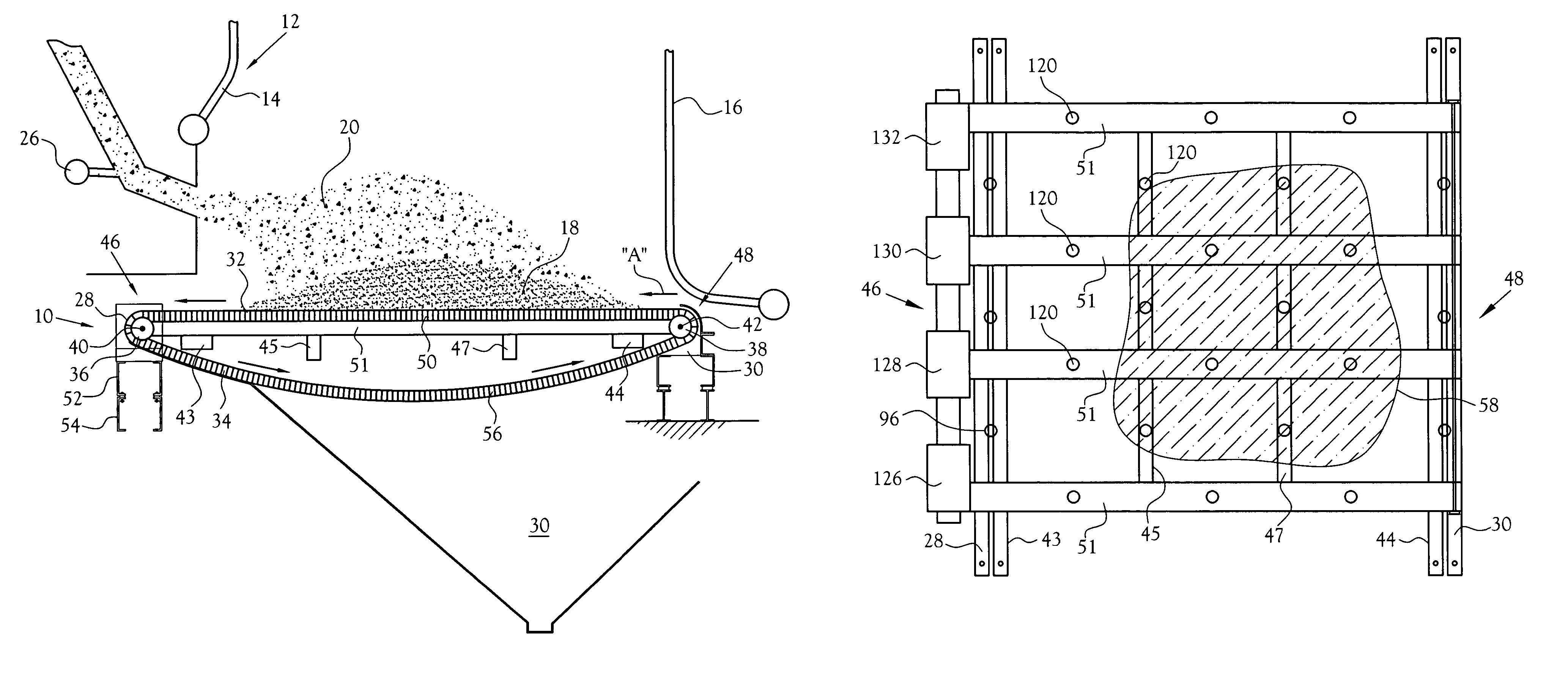
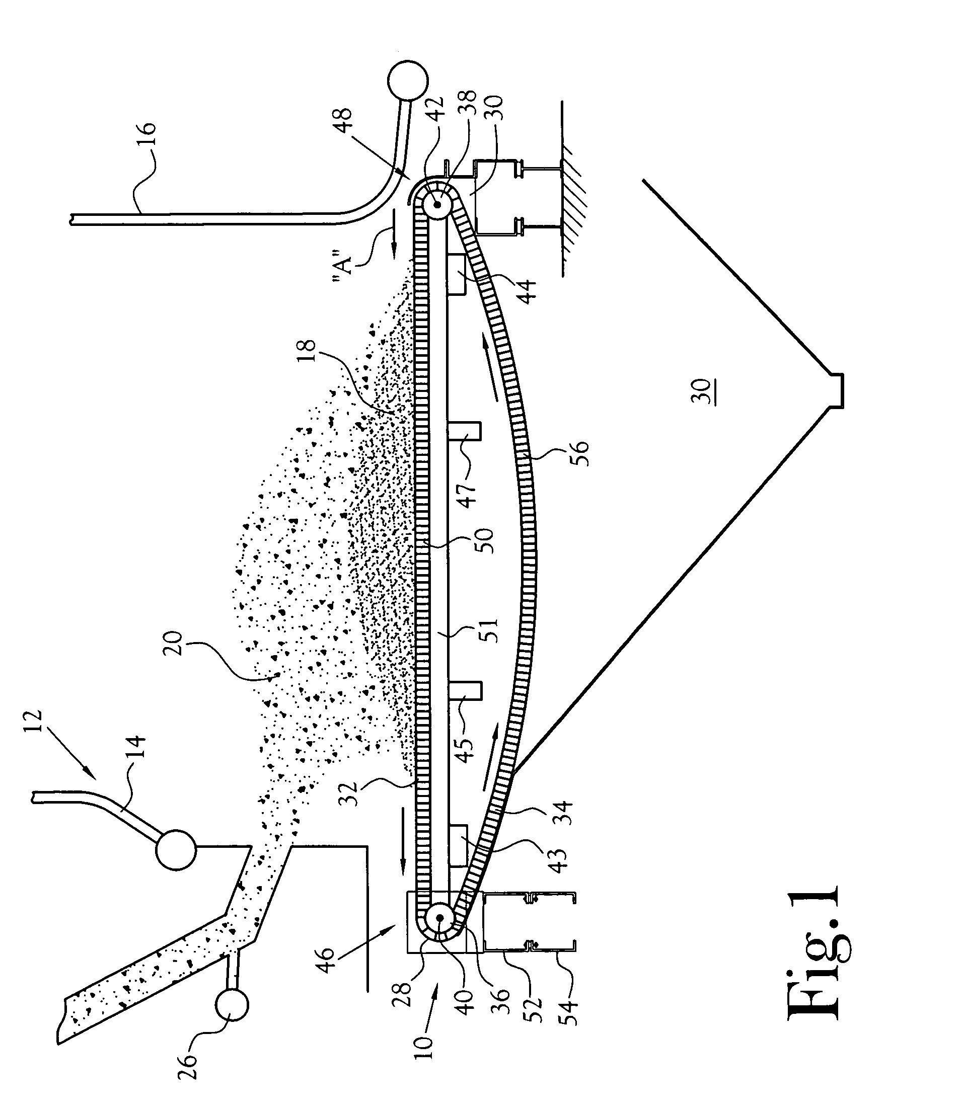
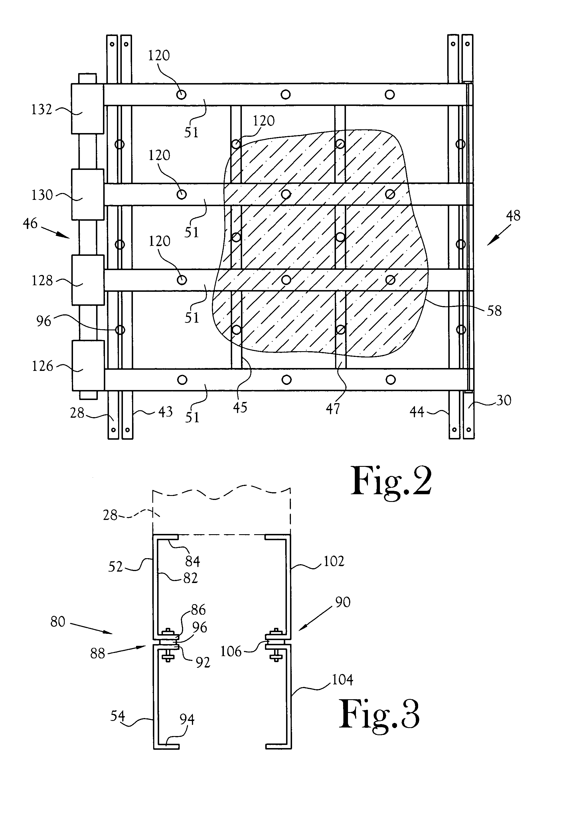
[0015]With reference to the several Figures, in the depicted embodiment of the present invention, there is depicted a schematic side elevation view of the bottom end 10 of a typical grate fired boiler 12. The depicted boiler includes water-filled side walls 14 and 16 disposed above and surrounding a burning mass 18 of particulate solids fuel 20. The heat from the burning fuel functions to heat the water in the side walls to either a selected temperature, most commonly, to convert the water into steam which desirably flows from the boiler at a target rate of flow. The target rate of flow is commonly set as a function of the demand for steam at some location or locations remote from the boiler. The burner is fired by fuel which includes particulate solids 20 blown onto the grate as by a blower or multiple blowers and, as needed or desired, oil or gas. Control over the rate of solids fuel admitted to the burner, and / or the type of fuel admitted, is controlled by one or more valves or l...


PUM


Abstract

Method and apparatus for sensing the overall and / or distribution of fuel weight disposed on the top surface of the grate of a grate-fired device and adjusting the fuel infeed as a function of the flow rate of steam generated by the boiler. A plurality of weight sensors are disposed remote from the grate at selected locations associated with the support for the grate and which provide signals which are convertible to useful representations of the overall weight and / or the distribution of fuel weight over the top surface of the grate in real time and independent of the forward movement of the grate and associated changes in the weight of the fuel on the grate at a given time.

Description

CROSS-REFERENCE TO RELATED APPLICATIONS[0001]Not ApplicableDEVELOPMENT[0002]Not ApplicableFIELD OF INVENTION[0003]This invention relates to the measurement and / or monitoring of fuel deposited on a grate fired boiler or like device.BACKGROUND OF INVENTION[0004]In grate fired boilers or like devices, fuel (solids) to be burned is fed onto a grate, at times along with combustion aids such as gas or oil. Herein the term “solids fuel” is at times referred to as “fuel”. The heat from the burning fuel is commonly used to generate steam. In the prior art, the rate of feeding of the fuel onto the grate has been manually controlled by an operator who uses visual observations, including use of cameras, and / or pyrometers as the tools for making judgment calls. It will be recognized that each of these methods of monitoring the progression of the burning of the fuel and the rate on incoming fuel to feed the combustion do not have the ability to provide a clear indication of the amount of material...

Claims


Application Information

Patent Timeline
Patent Type & Authority Patents(United States)
IPC IPC(8): F23K3/00F23N5/18F23H17/00F23K3/22F23N5/00
CPCF23H17/00F23K3/22F23G2900/55006F23N5/18F23K2203/104
Inventor JONES, ANDREW
Owner INT PAPER CO
Why Eureka
Try Eureka