Method for producing an incandescent light source and light source obtained according to such method

a technology of incandescent light source and light source, which is applied in the manufacture of electrode systems, electric discharge tubes/lamps, nanoinformatics, etc., can solve the problems of obtaining the aforesaid connection in a simple way, wider use of light sources with filament matrices, and manufacturing problems, so as to reduce dimensions, contain production costs, and low manufacturing defect rate

Inactive Publication Date: 2006-03-28
CENT RICERCHE FIAT SCPA
View PDF1 Cites 14 Cited by
  • Summary
  • Abstract
  • Description
  • Claims
  • Application Information

AI Technical Summary

Benefits of technology

[0014]Given that the dimensions and number of connections have considerable influence on the quantity of heat that is dissipated, and hence on the efficiency of the filament matrix, a first object of the present invention is to indicate a method that allows to obtain connections having extremely reduced dimensions.
[0015]Given that the operating temperature of the connections of the filament matrices is very high (˜2500° C.), a second aim of the present invention is to indicate a method that allows to obtain connections with an adequate ability to withstand such temperatures, without the production of polluting gases as a result of the operating temperature of the connections.
[0016]A third object of the invention is to indicate a method that, even in the presence of highly complex filament matrices, allows to obtain the connections in a simple manner, in order to contain production costs.
[0017]A fourth object of the invention is to indicate a method for obtaining filament matrices having very low manufacturing defect rate, in order to limit production waste.

Problems solved by technology

One of the reasons limiting the wider use of light sources with filament matrices is currently constituted by the difficulty in obtaining the aforesaid connection in a simple, effective and economical manner.
Another difficulty to overcome is given by the fact that, especially when the number of filaments in a matrix is high, there are manufacturing problems linked to their positioning.

Method used


Image

  • Method for producing an incandescent light source and light source obtained according to such method
  • Method for producing an incandescent light source and light source obtained according to such method
  • Method for producing an incandescent light source and light source obtained according to such method

Examples


Embodiment Construction

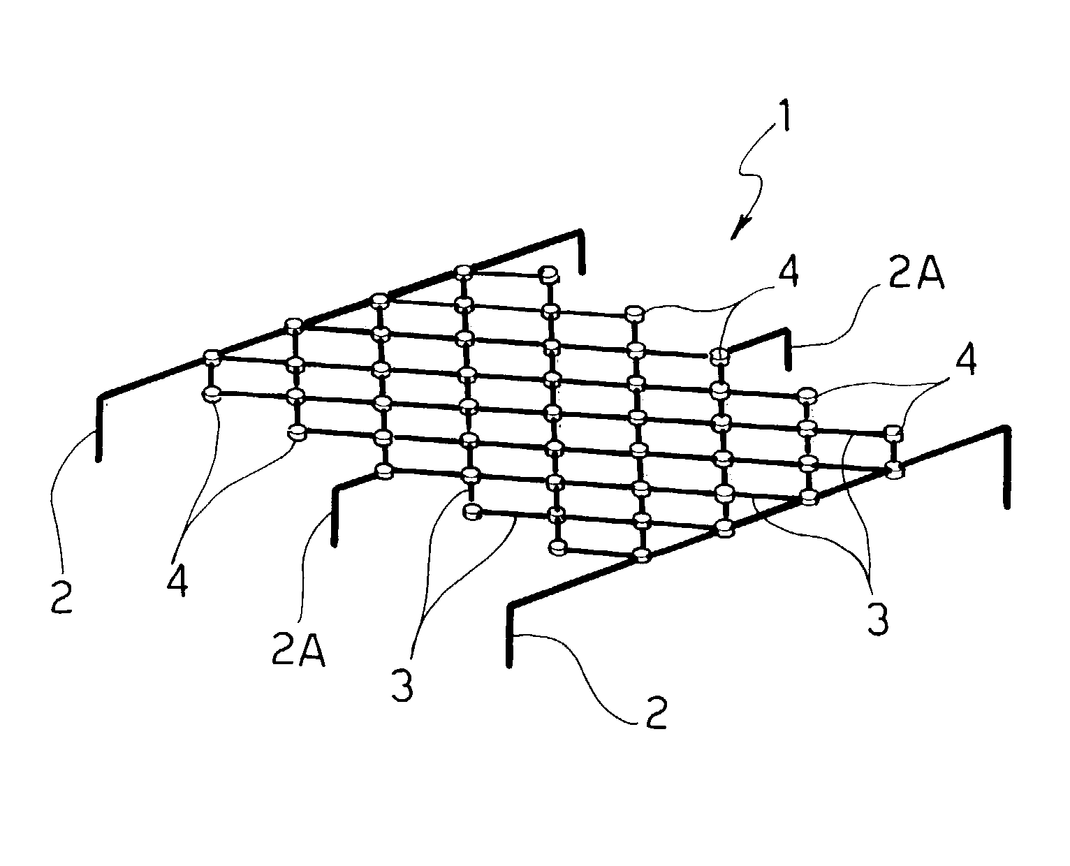
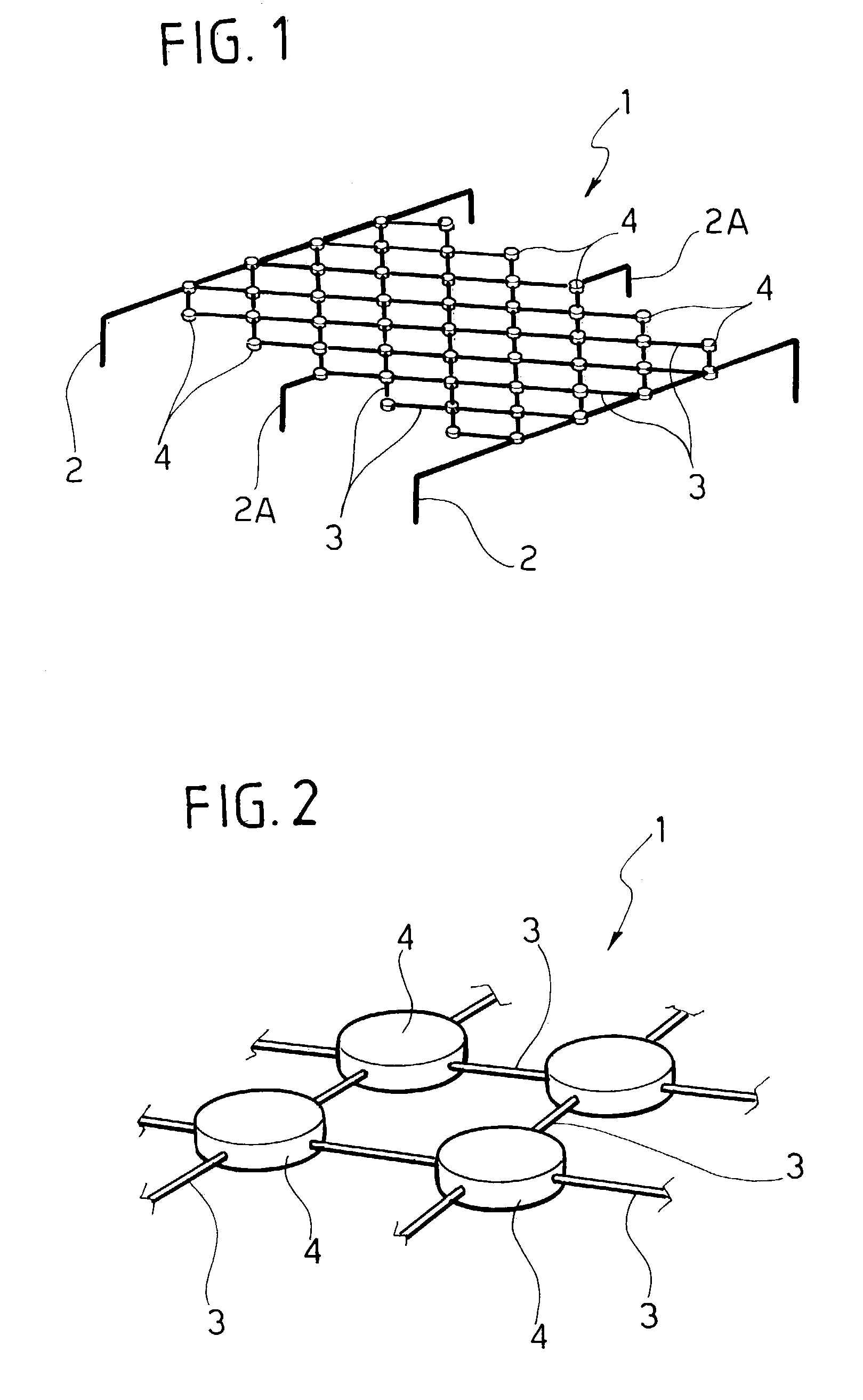
[0029]In FIG. 1, the reference number globally designates a filament matrix produced in accordance with the teaching of the present invention.

[0030]The matrix 1 comprises two lateral power supply conductors 2 made of metallic material and a plurality of micro-filaments 3, where the term “micro-filaments” means individual pieces of filament that emit light when an appropriate electrical current flows through them, reaching a temperature of about 2800° K.

[0031]The various micro-filaments 3 are arranged according to a “net” configuration, and are then mechanically and electrically connected to each other as well as to the conductors 2; the reference number 2A designates hooks for the positioning and support of the matrix 1, also connected to some micro-filaments 3. For this purpose, also with reference to FIG. 2, the reference number 4 designates the connections between some micro-filaments 3.

[0032]The elementary filament of the matrix 1 can be in different forms: individual wire, mult...


PUM

PropertyMeasurementUnit
operating temperatureaaaaaaaaaa
areaaaaaaaaaaa
lengthaaaaaaaaaa

Abstract

A method is described for producing a light source comprising a matrix of micro-filaments able to emit light by incandescence when powered by an electrical current. According to the invention, on the matrix electrical and/or mechanical connections are obtained by means of an agglomeration of carbon nanotubes at least partially ordered with respect to each other. The matrix can be formed extending a single uninterrupted wire, some segments whereof mutually cross.

Description

BACKGROUND OF THE INVENTION[0001]The present invention relates to a method for producing an incandescent light source and a light source obtained according to such method.[0002]The first working step followed for purposes of producing filaments for incandescent light sources typically consists of preparing a mixture of tungsten and metallic additives, which is subsequently sintered in the form of bars.[0003]The bars thus obtained are then subjected to hammering and drawing with successive passages, until obtaining a continuous wire with the desired diameter; said wire is subsequently wound in a spiral and cut to the required length to be ready, after a stabilising heat treatment, to be mounted onto a respective support to be inserted in the light source.[0004]In the case of common incandescent lamps, the filament is maintained in position thanks to respective end conductors and intermediate hooks; the conductors serve both as supports and to carry electrical power to the filament, a...

Claims


Application Information

Patent Timeline
Patent Type & Authority Patents(United States)
IPC IPC(8): H01K1/02H01J9/04H01K1/20H01K1/06C01B31/02H01K1/00H01K1/14H01K3/02
CPCB82Y10/00B82Y30/00H01K1/14H01K3/02H01K1/10Y10S977/95
Inventor PERLO, PIEROPAIRETTI, BARTOLOMEOVECA, ANTONINO
Owner CENT RICERCHE FIAT SCPA
Why Eureka
Try Eureka