Air duct seal for HVAC case

a technology of air duct seals and air ducts, which is applied in the direction of ventilation systems, heating types, vessel construction, etc., can solve the problems of foam being pushed out of position, air leakage, and method not without problems, and achieve the effect of improving the sealing structur

Active Publication Date: 2006-04-04
DENSO INTERNATIONAL AMERICA
View PDF5 Cites 91 Cited by
  • Summary
  • Abstract
  • Description
  • Claims
  • Application Information

AI Technical Summary

Problems solved by technology

However, this method is not without its share of problems.
Historically, foam breaks down and deteriorates with the passage of time, thus resulting in looser seals between mating parts that eventually results in the leaking of air where around the foam 18.
Still yet another disadvantage results when, during alignment or installation of the duct, the foam is pushed out of position, unbeknownst to the installer.
When this occurs, no seal or a seal that is easily blown out of position results between the mating parts and eventually results in the leaking of air where the foam 18 resides.
Regardless of the cause, the leaking of air results in lower blowing force and lower blowing volume into the automobile cabin.
This results in poor overall efficiency of an afflicted air-conditioning system.

Method used


Image

  • Air duct seal for HVAC case
  • Air duct seal for HVAC case
  • Air duct seal for HVAC case

Examples


Embodiment Construction

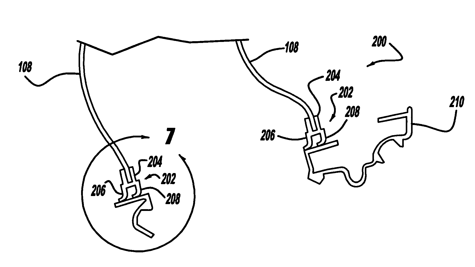
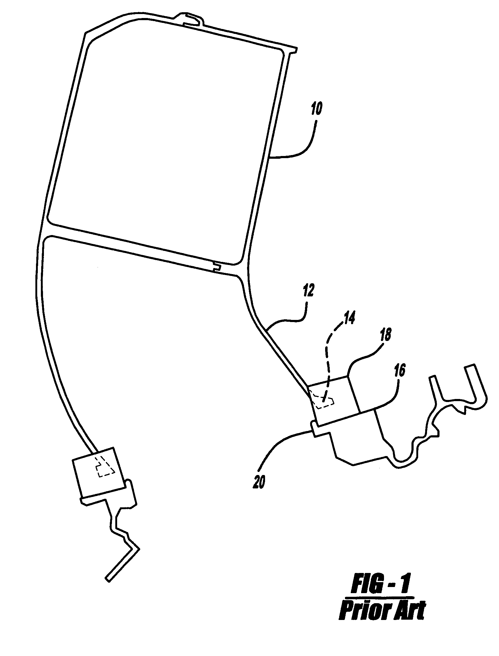
[0022]The following description of the preferred embodiments is merely exemplary in nature and is in no way intended to limit the invention, its application, or uses. The operative workings of the present invention will be described using FIGS. 2 through 11, while FIG. 12 provides a perspective view of an automobile 30 showing the general location of an engine with air-conditioning system 32 and an air-conditioning duct 108.

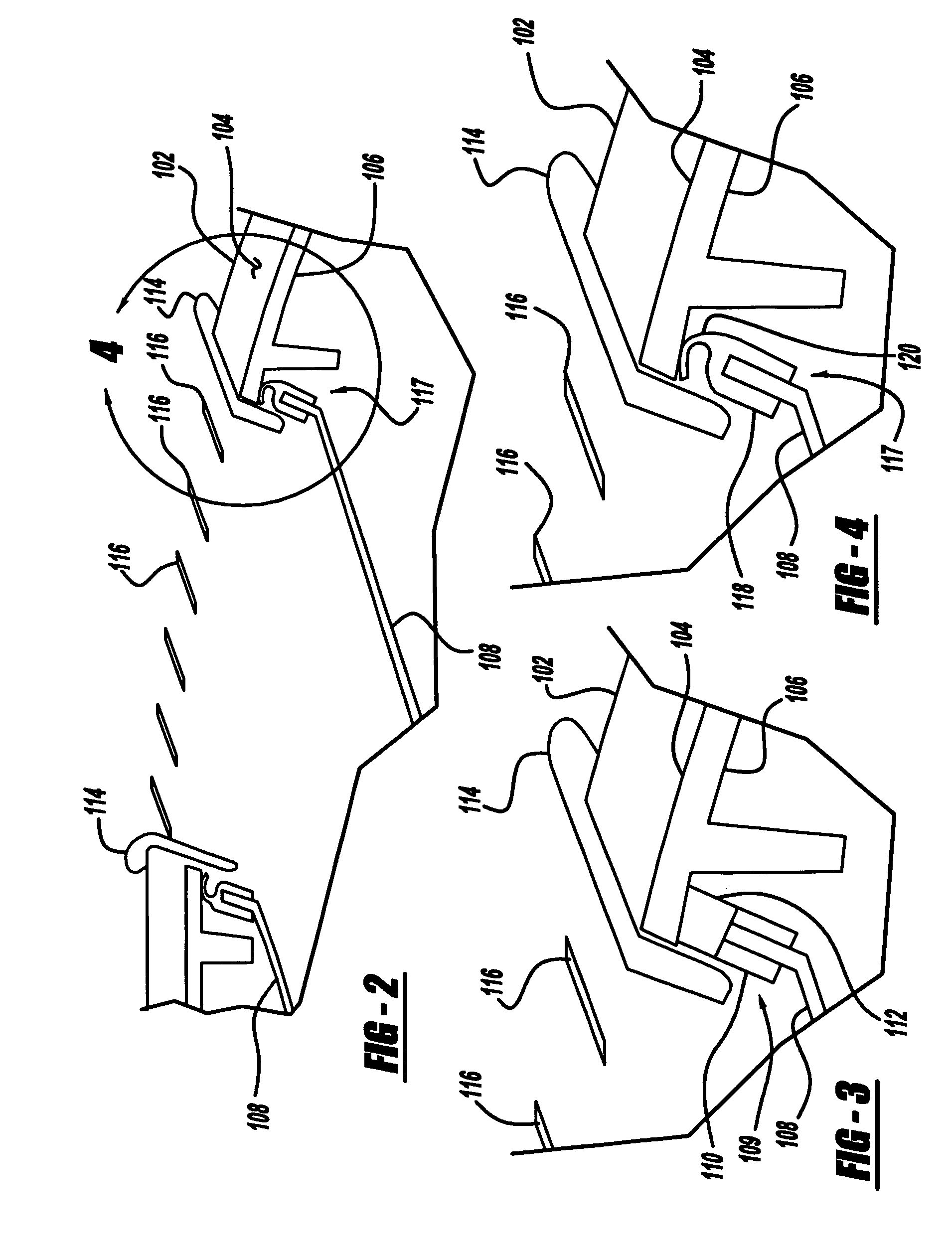
[0023]FIG. 2 is a cross-sectional view of a side window defroster outlet 100, which utilizes multiple parts, some of which are used to form a seal. In FIG. 2, the instrument panel (IP) 102 is retained or held in position by the instrument panel retainer (IPR) 114. The instrument panel 102 is constructed of a hard plastic or composite carrier 106 with an overlay of a soft cover 104 such that the soft cover 104 faces a user who occupies the front passenger seat in the passenger compartment of an automobile. The HVAC duct 108 interfaces with the instrument panel 102...


PUM


Abstract

An HVAC duct sealing system has an air duct wall, a sealing surface, such as an HVAC case, against which the air duct wall is biased, and a seal member interposed between the duct wall and the sealing surface. The seal member is interposed between the air duct wall and the sealing surface and is molded directly onto the air duct wall using a two-shot or double shot method of forming. The seal can be rubber or any flexible, pliable material capable of creating a seal with a surface. The seal has a seal base that is attached to and surrounds an end part and two sides of the air duct wall. The seal has a flexible tip portion extending from the seal base that is biased against and bends against the sealing surface in accordance with an amount of pressing force to create a seal. The flexible tip bends between 0 and 100 degrees from its pre-installation position.

Description

FIELD OF THE INVENTION[0001]The present invention relates to vehicular air duct seals, and more particularly to air duct seals on air ducts that abut an HVAC case and an air outlet device.BACKGROUND OF THE INVENTION[0002]In recent years, manufacturers and suppliers of heating ventilating and air-conditioning (HVAC) equipment for automobiles have invoked initiatives aimed at increasing the efficiency of air-conditioning systems. Specifically, one area that is the subject of an initiative is preserving and improving the seals between ductwork and casing utilized in the routing of air through the air-conditioning system. An improvement in the seals, connections and ductwork of the HVAC system results in improved efficiency of the air-conditioning systems.[0003]Foam is a traditional material used to connect ductwork pieces together and to connect ductwork to HVAC cases and air outlets. That is, foam is used as a sealing agent with the intention of creating a leak-proof seal between any ...

Claims


Application Information

Patent Timeline
Patent Type & Authority Patents(United States)
IPC IPC(8): B61D27/00
CPCB60H1/00564Y10S454/903B60H1/242
Inventor CROCKER, GLENN
Owner DENSO INTERNATIONAL AMERICA
Why Eureka
Try Eureka