Drive unit

a technology of drive unit and drive shaft, which is applied in the direction of couplings, furniture parts, gearing, etc., can solve the problems of high cost of resilient members and complex assembly of components of drive apparatus

Inactive Publication Date: 2006-04-04
AISIN SEIKI KK
View PDF11 Cites 25 Cited by
  • Summary
  • Abstract
  • Description
  • Claims
  • Application Information

AI Technical Summary

Problems solved by technology

However, the drive apparatus provided with the resilient members may cost much and assembling of components for the drive apparatus may become complex.

Method used


Image

  • Drive unit
  • Drive unit
  • Drive unit

Examples


first embodiment

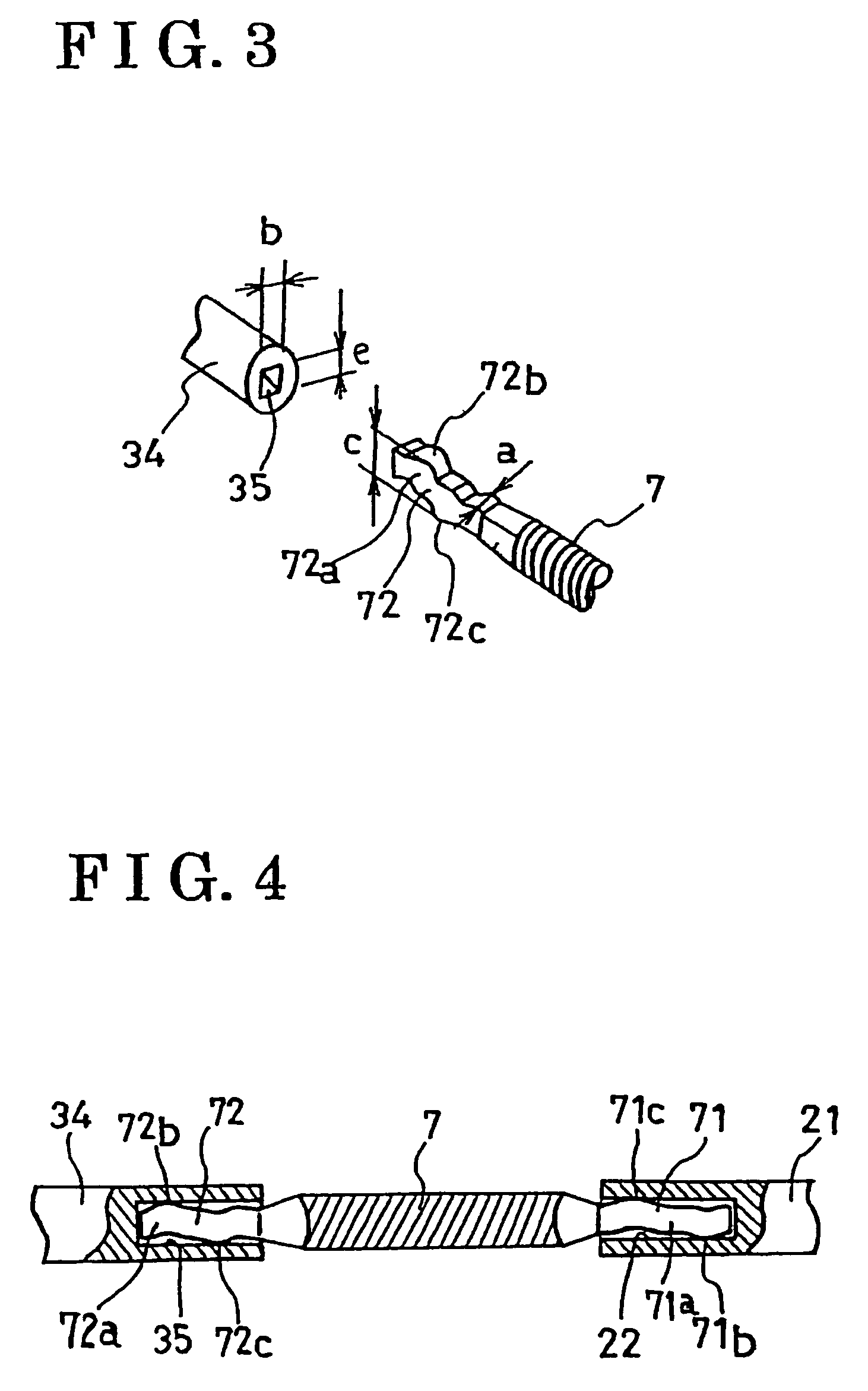
[0024]According to the above-described first embodiment of the present invention, the two projections are provided on each connecting portion of the cable 7. However, especially when the cable 7 is long, it is preferable that the greater number of projections can be provided on each connecting portion of the cable 7 so as to maintain the load between the connecting portions and the grooves in relation to stiffness of the cable 7.

[0025]According to the above-described first embodiment of the present invention, each projection is arranged symmetrical thereto about the central point in the longitudinal direction of the cable 7. However, the arranged position of each projection can be determined in light of the amount of torque to be transmitted. Therefore, the arrangement of each projection is not only limited to the first embodiment of the present invention as far as a requisite contact load can be assured.

second embodiment

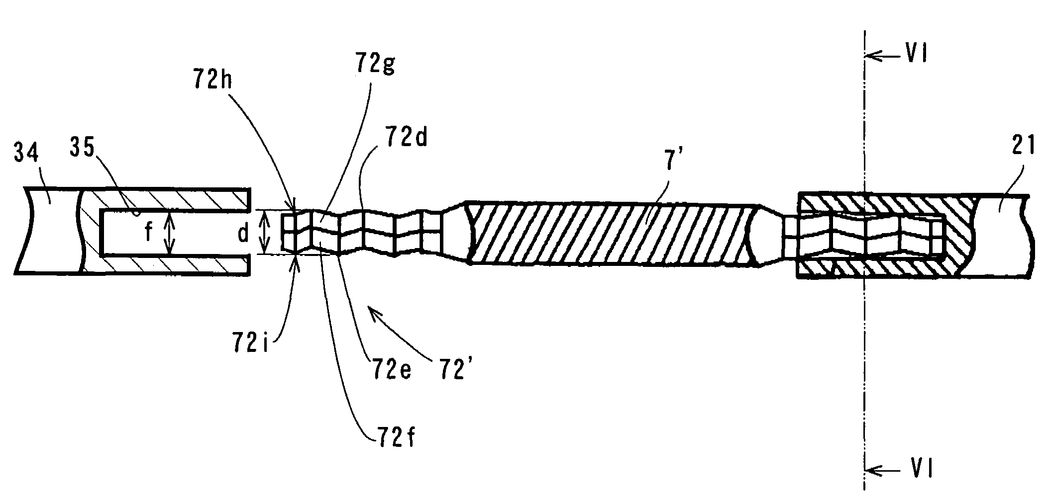
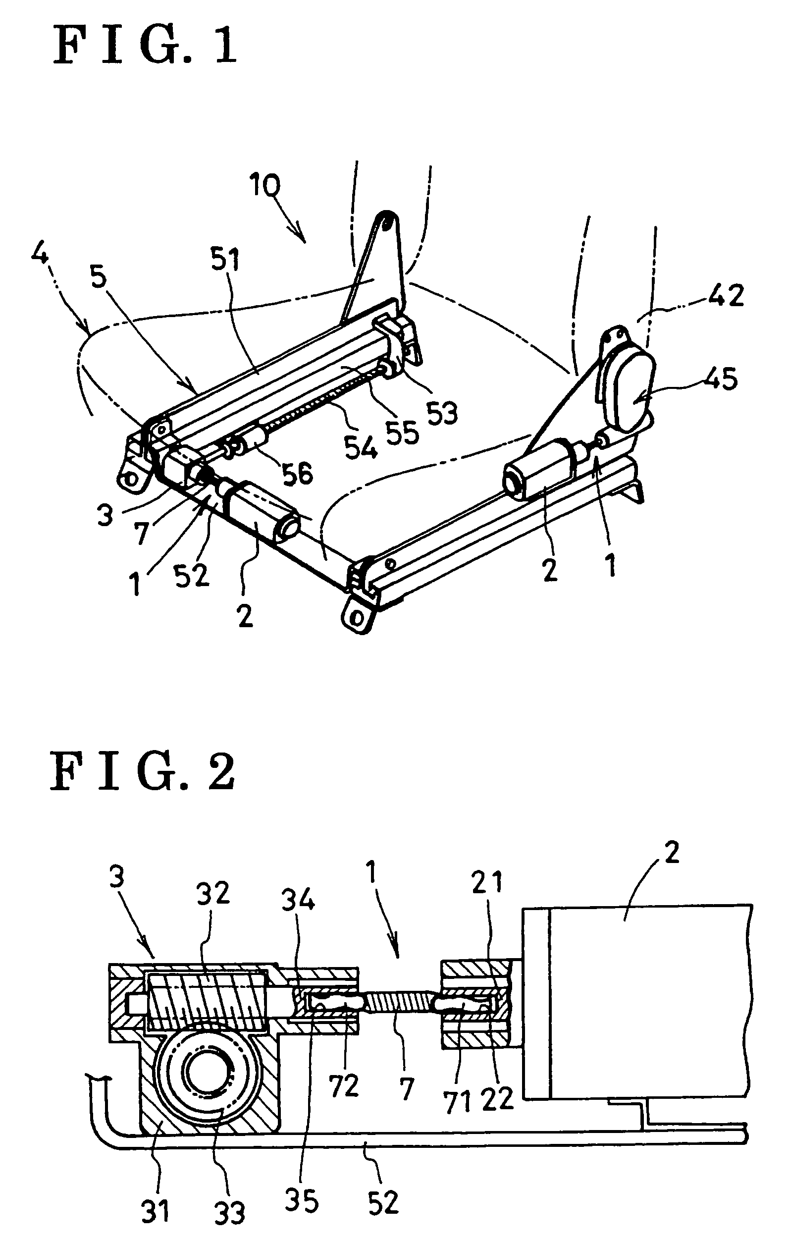
[0026]Next, the following description will be given for explaining the drive unit 1 according to the present invention with reference to FIGS. 5, 6 and 7.

[0027]FIG. 5 illustrates only one end of the cable 7′, and yet the other end thereof possesses the same structure as the one end thereof as shown in FIG. 7. A connecting portion 72′ of the cable 7′ possessing an approximately square-shaped cross section is integrally provided with two projections (i.e. projected portions) 72d with a predetermined distance therebetween on one of ridgelines 72h thereof. The connecting portion 72′ of the cable 7′ is also integrally provided with a projection (i.e. a projected portion) 72e on a ridgeline 72i opposite to the ridgeline provided with the two projections 72d. When the ridgeline provided with the two projections 72d is arranged at an upper side as illustrated in FIG. 5, the connecting portion 72′ undulates in a vertical direction thereof and extends in the longitudinal direction of the cabl...


PUM


Abstract

A drive unit includes a cable possessing connecting portions at both ends, one of the connecting portions inserted into a groove of an output shaft at one side, and the other one of the connecting portions inserted into a groove of an input shaft at the other side, wherein rotational torque from the output shaft is transmitted to the input shaft, and at least two projected portions provided on the respective connecting portions and arranged with a predetermined distance therebetween in a longitudinal direction of the cable, wherein the respective connecting portions possess bent-shaped structures and the two projected portions of the respective connecting portions become in contact with opposed surfaces of the respective grooves.

Description

CROSS REFERENCE TO RELATED APPLICATIONS[0001]This application is based on and claims priority under 35 U.S.C. §119 with respect to a Japanese Patent Application 2002-146094, filed on May 21, 2002, and 2003-075891, filed on Mar. 19, 2003, the entire content of which is incorporated herein by reference.FIELD OF THE INVENTION[0002]This invention generally relates to a drive unit provided with a flexible cable for transmitting rotational torque from an output shaft of a driving source to an input shaft of a driven apparatus.BACKGROUND OF THE INVENTION[0003]There is a conventional drive apparatus disclosed in a Japanese Patent Laid-Open Publication No. 9-86236. This disclosed drive apparatus is provided with a flexible cable for transmitting rotational torque from an output shaft of a motor to an input shaft of a speed reduction gear. More particularly, there are resilient members disposed in clearances defined between both ends of the flexible cable engagably inserted into respective gr...

Claims


Application Information

Patent Timeline
Patent Type & Authority Patents(United States)
IPC IPC(8): F16C1/08B60N2/02B60N2/06B60N2/22F16C1/00F16C3/02F16H1/16
CPCB60N2/0232B60N2/067B60N2/2231F16C1/08Y10T403/7003B60N2002/0236B60N2205/20F16C2326/08Y10T74/20462F16H1/16F16D2001/102B60N2/02253B60N2/02246
Inventor KOGA, YOSHITAKA
Owner AISIN SEIKI KK
Why Eureka
Try Eureka