Magnetic switch assembly

a technology of magnetic switch and assembly, which is applied in the direction of magnetic/electric field switch, mechanical actuation of burglar alarm, instruments, etc., can solve the problem that the reed switch is subject to unauthorized manipulation, and achieve the effect of less costly production and maintenan

Inactive Publication Date: 2006-04-04
MAGNASPHERE
View PDF13 Cites 23 Cited by
  • Summary
  • Abstract
  • Description
  • Claims
  • Application Information

AI Technical Summary

Problems solved by technology

It has been found that reed switches are subject to unauthorized manipulation through use of an external magnet.

Method used


Image

  • Magnetic switch assembly
  • Magnetic switch assembly
  • Magnetic switch assembly

Examples


Embodiment Construction

Embodiment of FIGS. 1–3

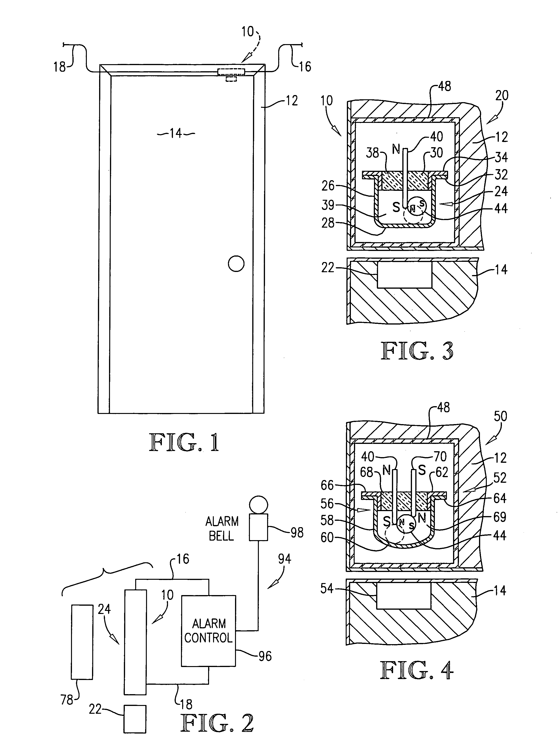
[0019]Turning now to the drawing, FIG. 1 illustrates a magnetic switch 10 (dashed lines) shown in use with a door frame 12 and door 14. Appropriate electrical leads 16, 18 are operatively coupled with the switch 10 as will be described below in more detail.

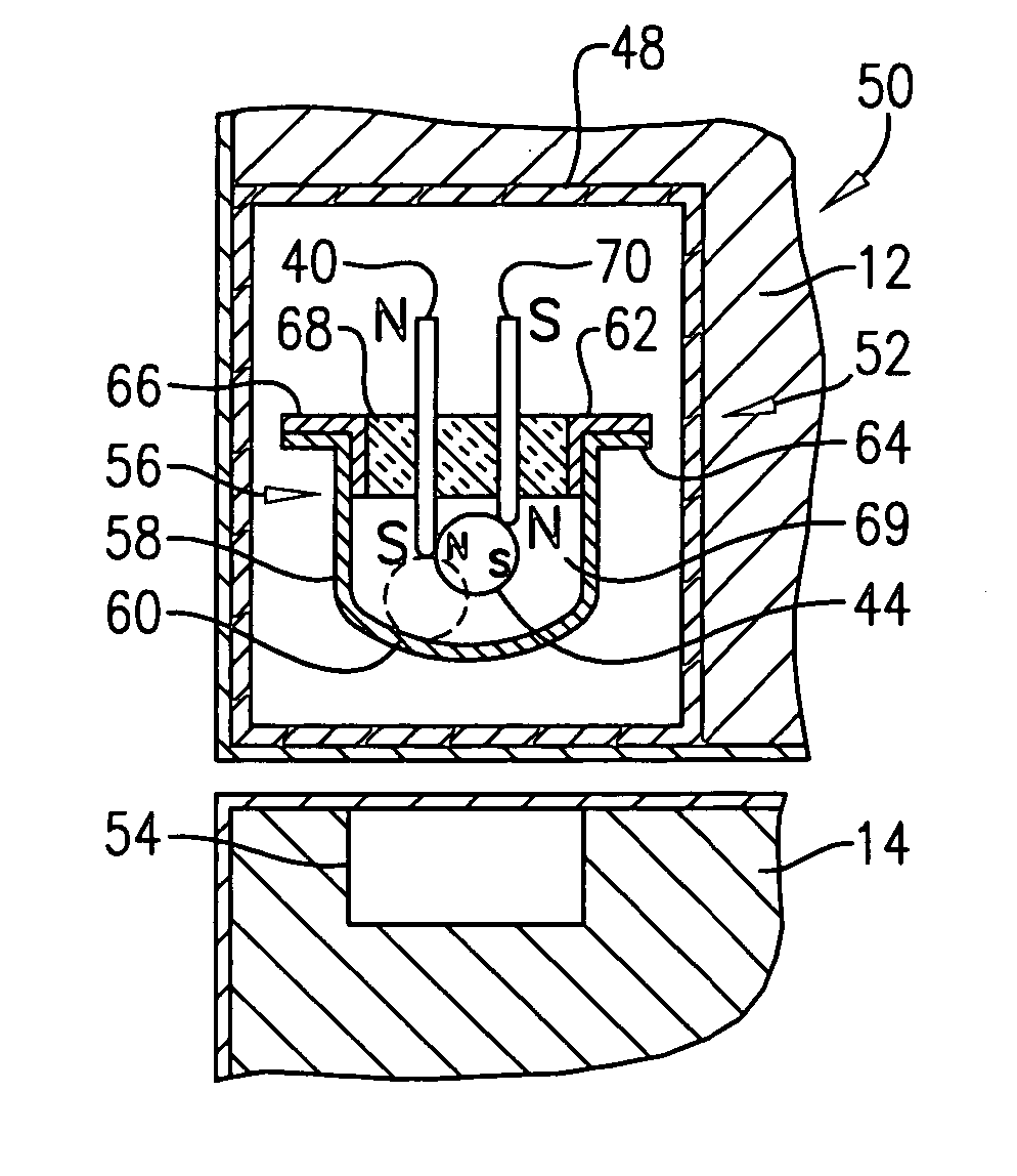
[0020]The switch 10 (FIG. 3) includes a switch assembly 20 designed to be secured to frame 12, as well as an attractive component 22 which is mounted to door 14. The switch assembly 20 in preferred forms includes a housing 24 having a circumscribing annular converging sidewall 26, an integral bottom wall 28 and a top cover 30. Preferably, the housing 24 presents a circumscribing flange 32 and is formed of a suitable electrically conductive stainless steel such as 304; however, it could also be formed of non-magnetic conductive materials such as copper. The top cover 30 includes an outboard flange 34 adapted to mate with flange 32, and a central glass or ceramic nonconductive plug 38. The flange 34 is prefera...


PUM


Abstract

A magnetic switch (10) for detecting relative movement between first and second members (12, 14) is provided which includes a switch assembly (20, 50, 70) for mounting in one of the members (12, 14), an attractive component (22, 54, 76) for mounting on the other member; the assembly (20, 50, 70) preferably includes plural switch elements (40, 26, 70, 56, 92, 80) and a conductive, shiftable body (44), whereas the component (22, 54, 76) is magnetically attractive to the body (44). The first switch elements (40, 70, 92) are preferably formed of a magnetically attractive material while the body (44) is fabricated from permanently magnetized material, so that the body (44) remains permanently magnetically coupled with the element(s) (40, 70, 92) in all positions of the body (44). Alternately, the switch assemblies (20, 50, 70) can be used as proximity detectors so as to generate a signal in the presence of an adjacent ferrometallic or permanently magnetized object (108).

Description

BACKGROUND OF THE INVENTION[0001]1. Field of the Invention[0002]The present invention is broadly concerned with magnetic switch devices operable to detect relative movement between first and second members, and as proximity detectors. The switches include a switch assembly for mounting to a first member and an attractive component being either itself the component to be detected or for mounting to the second member. The switch assembly preferably includes first and second spaced switch elements and an electrically conductive body shiftable between a first position in simultaneous contact with the first and second switch elements and a second position out of such simultaneous contact. The first switch element is formed of a magnetically attractive material, while the shiftable body is preferably permanently magnetized. When the first and second members are located so that the attractive component is proximal to the switch assembly, the shiftable body is moved to one of its position b...

Claims


Application Information

Patent Timeline
Patent Type & Authority Patents(United States)
IPC IPC(8): H01H9/00H01H36/00
CPCH01H36/00H01H2036/0086
Inventor WOODS, RANDALL
Owner MAGNASPHERE
Why Eureka
Try Eureka