Multifunctional tire pressure gauge

a tire pressure gauge and multi-functional technology, applied in the field can solve the problems of inconvenience for users in storage of conventional tire pressure gauges, limit the versatility of tire pressure gauges,

Inactive Publication Date: 2006-04-11
INTERFLOW CORP
View PDF6 Cites 19 Cited by
  • Summary
  • Abstract
  • Description
  • Claims
  • Application Information

AI Technical Summary

Problems solved by technology

However, the conventional tire pressure gauge only has a single function, thereby limiting the versatility of the tire pressure gauge.
In add

Method used


Image

  • Multifunctional tire pressure gauge
  • Multifunctional tire pressure gauge
  • Multifunctional tire pressure gauge

Examples


Embodiment Construction

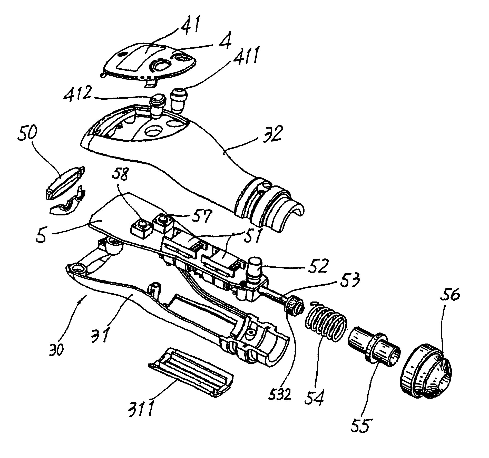
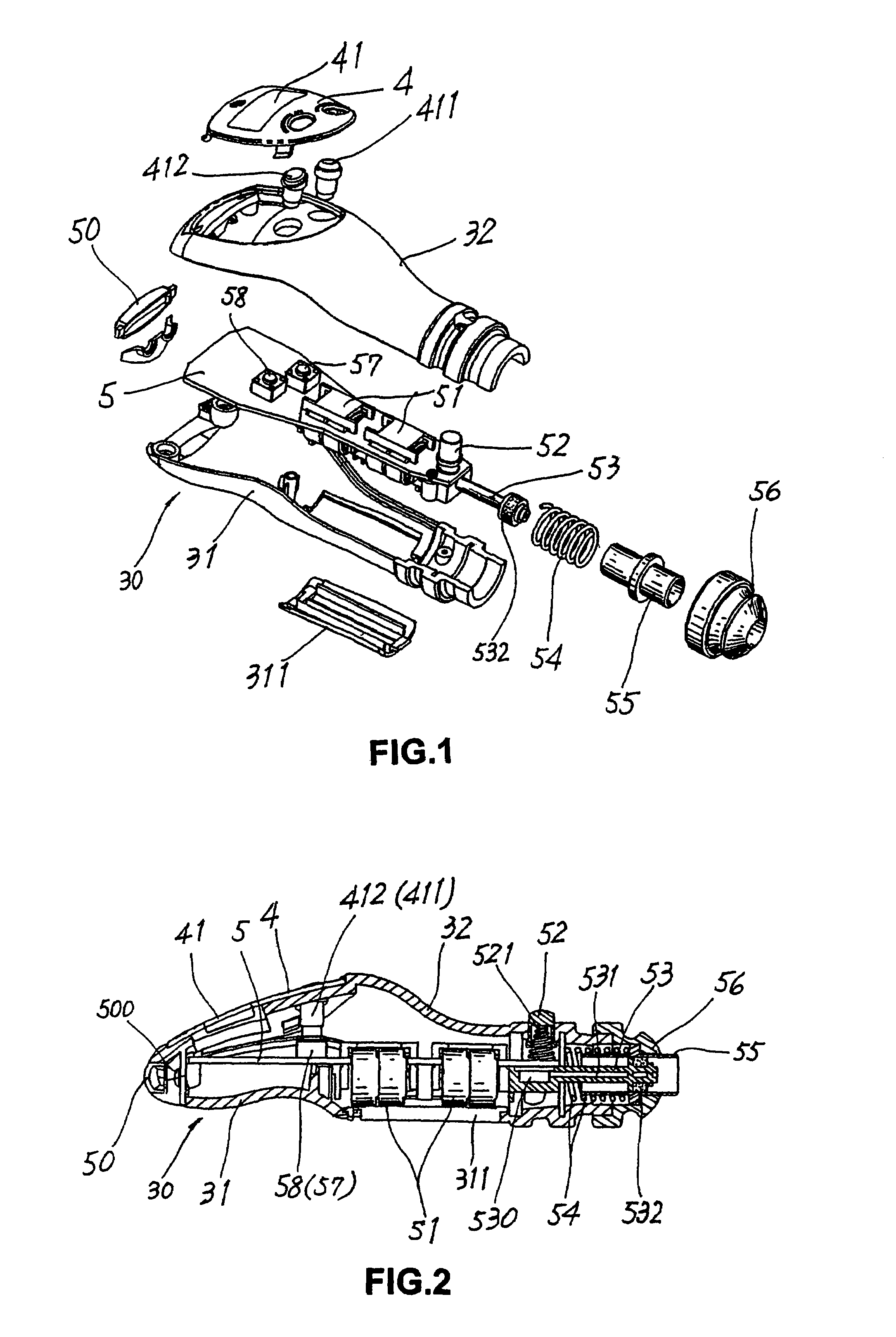
[0017]Referring to the drawings and initially to FIGS. 1 and 2, a tire pressure gauge in accordance with the preferred embodiment of the present invention comprises a housing 30, a circuit board 5 mounted in the housing 30, an air pipe 53 (or measuring connector) mounted on and extended from an end of the circuit board 5, a plug 56 mounted on and protruded outward from a first end of the housing 30, a hollow positive pole press rod 55 movably mounted on the air pipe 53 and having a first end connected to a first side of the circuit board 5 and a second end protruded outward from the plug 56, a first elastic member 54 mounted on the positive pole press rod 55 and having a distal end connected to the first side of the circuit board 5, a negative pole press rod 52 movably mounted on the first end of the housing 30 and having a first end connected to a second side of the circuit board 5 and a second end protruded outward from the housing 30, a second elastic member 521 mounted on the ne...


PUM


Abstract

A multifunctional tire pressure gauge for a car functions to measure the inner temperature of the car, the voltage of the car battery and the tire pressure of the tire. Thus, when the plug is inserted into the cigarette lighter of the car, the tire pressure gauge can be used to measure the temperature of the inside of the car and the voltage of the car battery simultaneously. In addition, after the plug is removed from the cigarette lighter, the tire pressure gauge functions as a portable tire pressure gauge.

Description

BACKGROUND OF THE INVENTION[0001]1. Field of the Invention[0002]The present invention relates to a tire pressure gauge, and more particularly to a multifunctional tire pressure gauge.[0003]2. Description of the Related Art[0004]A conventional tire pressure gauge in accordance with the prior art shown in FIGS. 4 and 5 comprises a main body 1, a measuring connector 11 mounted on a first side of the main body 1, a display 12 and a switch 13 mounted on a second side of the main body 1 respectively, an air pipe 110 mounted in the measuring connector 11 and having an inside formed with an air hole 111 and a front end provided with a pressing end 113, and a soft gasket 112 mounted on a periphery of the air pipe 110 and located beside the pressing end 113.[0005]When the conventional tire pressure gauge is mounted on the air valve 20 of a tire 2, the pressing end 113 of the air pipe 110 presses the air nozzle 21 of the air valve 20 to move inward to drain the air from the air valve 20 of the...

Claims


Application Information

Patent Timeline
IPC IPC(8): B60C23/02
CPCG01L19/0092G01L17/00
Inventor CHEN, JUI-YU
Owner INTERFLOW CORP
Why Eureka
Try Eureka