Tire pressure gauge

a tire pressure sensor and tire pressure technology, applied in the direction of inflated body pressure measurement, force measurement by elastic gauge deformation, instruments, etc., can solve the problems of limiting the application range of the sensor, affecting the wear and tear of the sensor, and the failure of the installation enclosure, so as to achieve the effect of high universality of the product and better wearability

Inactive Publication Date: 2017-09-21
STEELMATE CO LTD
View PDF6 Cites 8 Cited by
  • Summary
  • Abstract
  • Description
  • Claims
  • Application Information

AI Technical Summary

Benefits of technology

[0009]Pivotal connection between the tire pressure gauge body and gas nozzle assembly is realized, thus realizing adjustment of the angle between the stem and body to adapt tires with different hub mounting surfaces and leading to high universality of the product. Moreover, as the second axle bed and first threaded embossment are made of metal, the connection between the enclosure and gas nozzle is reliable and better wear-ability is obtained.

Problems solved by technology

However, a prior art tire pressure sensor fails to adjust the angle between itself and stem.
This limits application range of the sensor, and the sensor is restricted to be mounted in a specific wheel hub.
In addition, there are kinds of different types of hubs, and accordingly, for a tire pressure sensor where the angle between the stem and sensor enclosure is unchanged, following limitations exist: in some situations, the bottom of the sensor enclosure may interfere and rub with the bottom of hub, thus the enclosure being subject to huge external force and even causing installation failure of the enclosure; and in other situations, a large gap may exist between the sensor enclosure and bottom of the wheel hub, thus making it hard for the hub to effectively support the enclosure and causing the enclosure to occupy large space and accordingly, the enclosure possibly withstands excessive load which results in crack or loosening of the enclosure from the stem.

Method used


Image

  • Tire pressure gauge
  • Tire pressure gauge
  • Tire pressure gauge

Examples


Embodiment Construction

[0026]Various embodiments of the invention are described below in greater details with reference to the drawings.

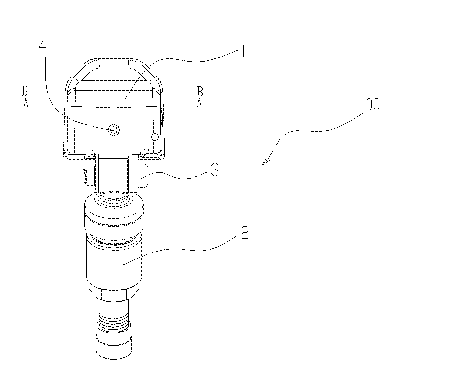
[0027]FIGS. 1-7 collectively show a tire pressure gauge 100 of the invention for being mounted on a wheel hub of a car so as to detect gas pressure inside the tire and transmitting signals representing the pressure to outside, said signals being received and displayed by a tire pressure displaying device.

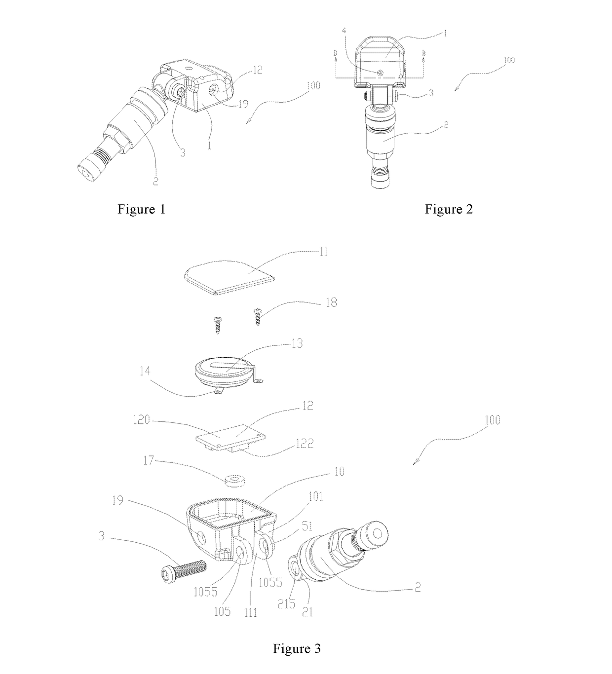
[0028]Please refer to FIG. 3. The tire pressure gauge 100 includes a body 1 and a gas nozzle assembly 2 pivotally connected with the body 1.

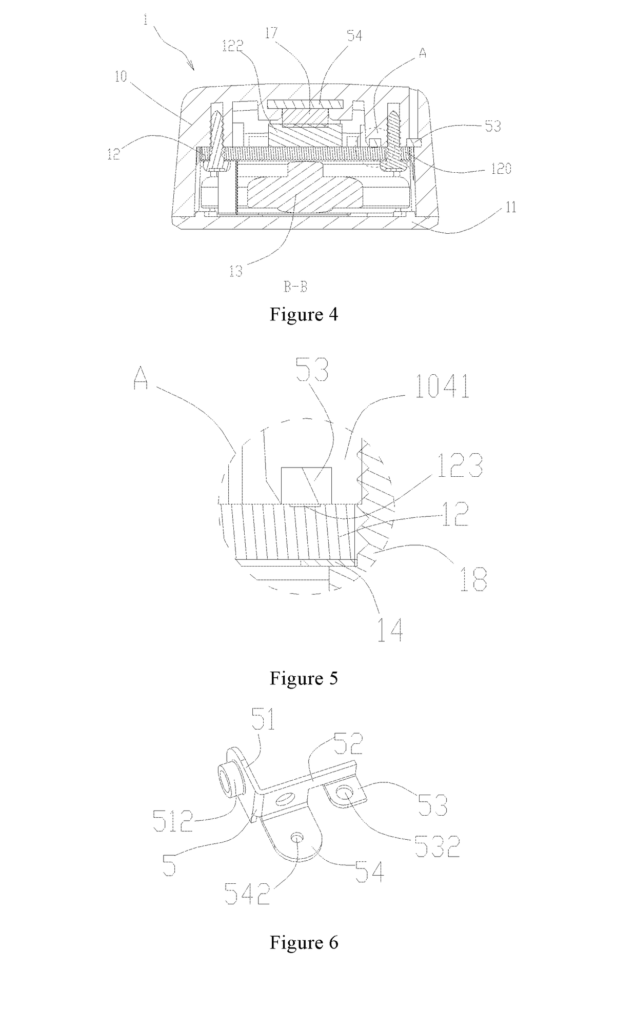
[0029]The body 1 includes an enclosure 10, a PCB assembly 12 disposed in the enclosure 10, a battery 13 also disposed in the enclosure 10, and a metal connection member 5 partially extended out of the enclosure 10. The battery 13 supplies power to the PCB assembly 12 (that is, the battery 13 supplies power to the body 1).

[0030]The enclosure 10 includes a bottom plate 104, a front panel 101, a rear panel 102, a pair of side plates 103 ...


PUM


Abstract

A tire pressure gauge includes a body and a gas nozzle assembly pivotally connected with the body. The body includes an enclosure, a PCB assembly disposed in the enclosure, a battery, and a metal connection member; the enclosure includes a front panel, a first axle hole is defined in the first axle bed; the metal connection member includes a second axle bed corresponding to the first axle bed, another first axle hole is defined in the second axle bed, a first threaded embossment is formed on the second axle bed, a swing gap is defined between the first and second axle beds; and the gas nozzle assembly includes a swing head, and a screw passes through the first axle hole, second axle hole, and another first axle hole, and then connects with the first threaded embossment.

Description

FIELD OF THE INVENTION[0001]The present invention involves field of tire pressure monitoring and more particularly, involves a tire pressure gauge.BACKGROUND OF THE INVENTION[0002]To ensure safe driving of vehicle, a popular practice is to mount a tire pressure monitoring system (TPMS) in a car for real time monitoring gas pressure and temperature of the tires. In operation of the TPMS, a tire pressure sensor is installed on a gas nozzle of a hub of each tire. The system also includes a sensor enclosure, a stem, kinds of sealing members and fasteners. Components for example a tire pressure-sensing element and battery are contained in the sensor enclosure. No matter whether the car is moving, the tire pressure sensors real time automatically monitor pressure and temperature of the tires, and provide alarm when the tire pressure and temperature is abnormal, thus avoiding traffic accidents due to malfunction of the tires and keeping safe operation of the car.[0003]However, a prior art ...

Claims


Application Information

Patent Timeline
Patent Type & Authority Applications(United States)
IPC IPC(8): B60C23/04
CPCB60C23/0498B60C23/0494G01L17/00G01L1/04
Inventor LI, ANPEISU, ZHIQIANG
Owner STEELMATE CO LTD
Why Eureka
Try Eureka