Temporary attachment tire pressure gauge

a technology of pressure gauges and tires, applied in the direction of tire measurements, vehicle components, transportation and packaging, etc., can solve the problems of adverse effects on vehicle handling, tire wear rate increase, and fuel economy adverse effects

Inactive Publication Date: 2007-10-23
CREATIVE AUTO RESOURCES
View PDF27 Cites 8 Cited by
  • Summary
  • Abstract
  • Description
  • Claims
  • Application Information

AI Technical Summary

Benefits of technology

[0009]With this invention a gauge is provided which can both sense pressure within a tire or other air filled chamber and allow air (or other gas) to be filled into the tire with the gauge remaining in place upon a valve stem of the tire. The gauge includes a pressure sensor, such as a Bourdon tube, which is shielded by a sensor protector so that over-pressure fill air does not damage the sensor element while the fill air is passing through the gauge and into the tire.
[0010]The gauge generally includes a receiver adapted to be mounted to a valve stem of a tire or other chamber to be filled with air. This receiver is preferably configured so that it can be mounted to the valve stem and remain upon the valve stem both during a filling procedure and preferably also after the filling procedure and during operation of the tire. A valve core is also provided on the gauge with a fluid path extending between the valve core and the receiver so that air or other gas from a source of fill air / gas coupled to the valve core can pass from the valve core, along the path, through the receiver and into the tire without requiring removal of the gauge.
[0011]A pressure sensor, such as a Bourdon tube, has an open inner end thereof coupled to a port adjacent the path between the valve core and the receiver. The sensor protector is adjacent this port so that over-pressure air is prevented from passing into the Bourdon tube or other pressure sensor.

Problems solved by technology

If tire pressure is not maintained, fuel economy is adversely affected and rates of tire wear increase.
Additionally, handling of the vehicle can be adversely affected and the potential for abrupt failure of the tire is increased.
One of the difficulties encountered in such regular tire pressure monitoring is that a significant amount of time is associated with monitoring tire pressure.
On a vehicle with multiple tires, this basic routine can be significantly time consuming, decreasing the likelihood that tire pressure monitoring will occur on a sufficiently frequent basis.
Compounding this difficulty is the inconvenience encountered when tire pressure is low and air needs to be added to the tire.
While this solves a portion of the problem, the difficulty associated with adding air to the tire is not alleviated.
Bourdon tubes are susceptible to de-calibration or other damage if gas having a pressure greater than a maximum pressure for which the Bourdon tube is calibrated is encountered by the Bourdon tube or other pressure sensor.
Other failure modes also exist including rupture of the Bourdon tube so that it does not provide any reading whatsoever thereafter.
The problem of Bourdon tube damage and de-calibration is particularly pernicious in that in some over-pressure failure modes, the Bourdon tube may appear to be functioning properly, when in fact it has become de-calibrated.
However, such high pressure fill air / gas sources provide a serious threat to the proper function of a Bourdon tube, or many other types of pressure sensors.
The patents to LaSalle and Hunt fail to address this problem.
While some prior art gauges are designed to be somewhat permanently mounted to the valve stem, such as by threading onto the threads of the valve stem, such semi-permanent attachment disadvantageously involves a separate gauge for each of the wheels of a vehicle or complex attachment / detachment repetition.

Method used


Image

  • Temporary attachment tire pressure gauge
  • Temporary attachment tire pressure gauge
  • Temporary attachment tire pressure gauge

Examples


first embodiment

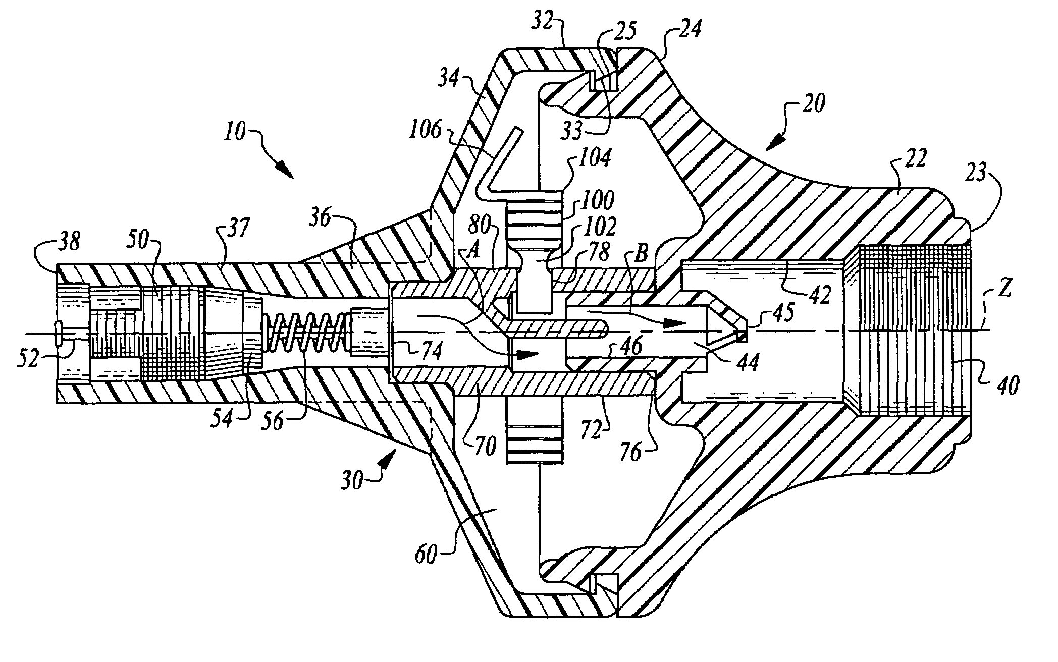
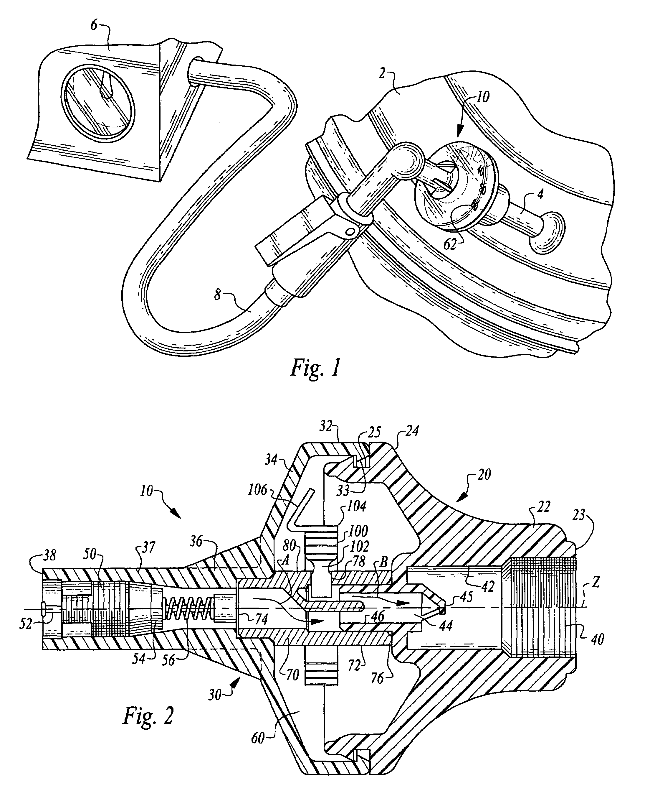
[0062]Referring to the drawings, wherein like reference numerals represent like parts throughout the various drawing figures, reference numeral 10 (FIGS. 1 and 2) is directed to a tire pressure gauge 10 according to this invention. The gauge 10 is configured to be mountable to a chamber of compressed air or gas, such as a tire 2 through a valve stem 4 thereof. The gauge 10 is also configured to allow compressed air or other gas to be delivered into the tire 2 through the gauge 10. For instance, an air compressor 6 can supply compressed air through a hose 8 which is attachable to the gauge 10 for filling of the tire 2 through the gauge 10. In this way, the gauge 10 does not need to be removed during the tire 2 filling process. Rather, the gauge 10 can remain upon the tire 2 during the filling process, and preferably also during operation of the tire 2. The gauge 10 is additionally configured to protect a pressure sensor, such as a Bourdon tube 100, within the gauge 10 from over-press...

fourth embodiment

[0095]While the extension tube 482 is shown in this fourth embodiment extending perpendicular to the central axis Z, the extension tube 482 could include a bend therein or otherwise be configured so that it faces upstream either partially or completely, and with the restriction plate 486 at the free end 484 of the extension tube 482.

[0096]With particular reference to FIGS. 16-19, details of a gauge 510 according to a fifth embodiment are described. This gauge 510 is similar to the gauge 10 of the first embodiment (FIGS. 1 and 2) except that the venturi protector 80 of the first embodiment is replaced with the stopper protector 580 of the gauge 510. Details of the stopper protector 580 are described herein, with other portions of the gauge 510 preferably remaining similar to those described above with respect to the gauge 10 of the first embodiment, except where otherwise provided.

[0097]In particular, the stopper protector 580 includes the standard column 70 modified from its depicti...

sixth embodiment

[0104]With particular reference to FIGS. 20-24, details of a sixth embodiment gauge 610 featuring temporary attachment are described. This temporary attachment gauge 610 is preferably only different from previous embodiments within a modified lower body 620 of the gauge 610. Other portions of the gauge 610 are shown in phantom and could be configured to correspond with any of the previous embodiments of this invention or other gauge structures of other known prior art or future developed gauge structures.

[0105]The modified lower body 620 is particularly configured to facilitate temporary but secure attachment of the gauge 610 to the valve stem 4 of a tire 2. Such a construction facilitates use of a single temporary attachment gauge 610 on a first tire to be evaluated and / or filled, and then having the gauge 610 be readily removable and reattached to a separate tire for evaluation of the second tire, and so on. Thus, the gauge 610 is optimized for use as a single gauge on a multiple ...


PUM


Abstract

A gauge is provided for monitoring pressure of air within a tire or other gas containing chamber. A gauge includes a receiver attachable to a valve stem of the tire. A valve core is also provided on the gauge through which fill air can be directed. In this way, the gauge does not need to be removed during filling of the tire with air. A pathway extends from the valve core to the receiver within the gauge. A pressure sensor, such as a Bourdon tube, is coupled to this pathway and monitors pressure within the tire. A lower body of the gauge includes a latching element which can be manually actuated to temporarily mount the gauge to the valve stem. The latching element can be in the form of levers which rotate and act as a toggle to engage the valve stem and secure the gauge to the valve stem.

Description

CROSS-REFERENCE TO RELATED APPLICATIONS[0001]This application claims benefit under Title 35, United States Code § 119(e) of U.S. Provisional Application No. 60 / 684,663 filed on May 25, 2005.FIELD OF THE INVENTION[0002]The following invention relates to pressure gauges and particularly pressure gauges adapted to be attached to tires and other similar gas filled chambers. More particularly, this invention relates to pressure gauges which include a valve core which allows fill air to be routed through the gauge and into the chamber to which the gauge is attached, and which additionally feature latching elements for quickly, securely but temporarily mounting the gauge to the valve stem; so that the gauge can be held thereon without requiring the gauge to be separately held by a user during introduction of fill air through the gauge and into the valve stem.BACKGROUND OF THE INVENTION[0003]One important criteria for safely operating a motor vehicle is the maintenance of proper pressure wi...

Claims


Application Information

Patent Timeline
Patent Type & Authority Patents(United States)
IPC IPC(8): B60C23/02
CPCB60C23/0496
Inventor RUTHERFORD, ROBERT B.
Owner CREATIVE AUTO RESOURCES
Why Eureka
Try Eureka