Microstimulator neural prosthesis

a microstimulator and neural prosthesis technology, applied in electrotherapy, therapy, etc., can solve the problems of inefficient coupling of input power and device, inefficient bowel and bladder area autonomic problems, and high cost of implementation, and achieve the effect of improving the efficiency of the system, reducing the cost of implementation, and improving the quality of li

Inactive Publication Date: 2006-04-11
VETERANS AFFAIRS DEPT OF
View PDF7 Cites 89 Cited by
  • Summary
  • Abstract
  • Description
  • Claims
  • Application Information

AI Technical Summary

Benefits of technology

[0008]In the exemplary embodiment, the control component has a relatively fast temporal response and the pulse generating circuit is triggerably responsive to the relatively fast temporal characteristic for producing output pulses.
[0009]In accordance with another feature of the invention, the power component and control component of the RF signal are selectively temporally separated so that in one phase, the strength of the input pulse is determined and thereafter the pulse is triggered.

Problems solved by technology

Autonomic problems occur in areas of the bowel, bladder and respiratory systems following spinal cord injuries.
Such techniques suffer from problems associated with the inefficient coupling of the input power to the device.
Such systems are often inefficient and expensive to implement.
In addition, such systems do not provide for versatile controls.
Also, conventional devices have limited capability to deliver relatively high currents over prolonged application cycles.
Such systems may not be satisfactory for use in connection with bowel stimulation, which may require application of relatively high currents during a treatment period for as long as 30 minutes.

Method used


Image

  • Microstimulator neural prosthesis
  • Microstimulator neural prosthesis
  • Microstimulator neural prosthesis

Examples


Embodiment Construction

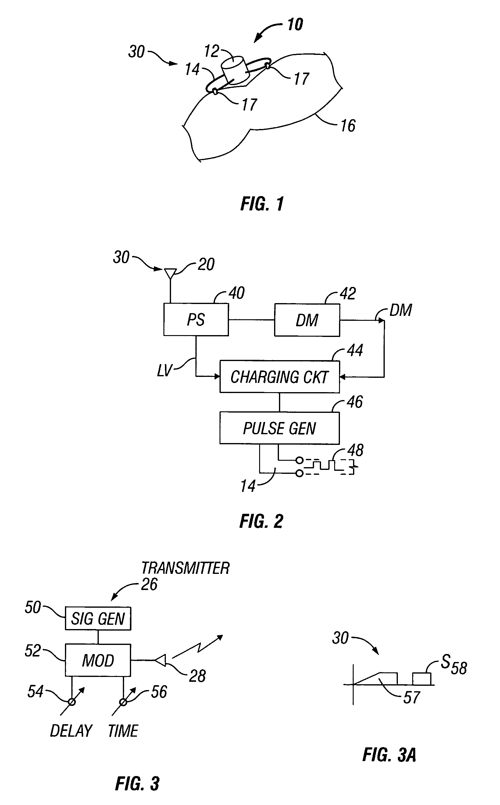
[0016]FIG. 1 illustrates a microstimulator 10 in accordance with the present invention, which comprises an encapsulated device 12 having external electrodes 14 which may be sutured or attached to an excitable organ or muscle, such as the bowel 16 of a patient, as shown in the drawing. The microstimulator has an internal antenna (FIG. 2) for receiving an input radio frequency (RF) input signal 30. A transmitter 26, shown in FIG. 3, having a transmitter antenna 28, produces the RF signal 30 which powers and controls the microstimulator 10. According to the invention, when treatment is necessary, the transmitter antenna 28 is located proximate to the patient and the implanted microstimulator 10 which is located near the internal organ 16 is powered and controlled wirelessly by the transmitter 26.

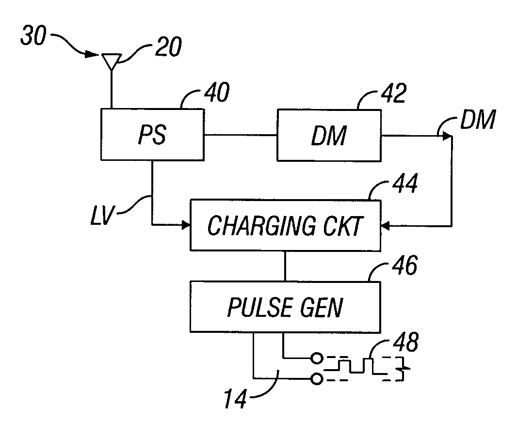
[0017]FIG. 2 illustrates the microstimulator 10 in schematic form. The antenna receiver 20 receives the RF signal 30 and couples the signal to a power supply 40 which produces a high voltage (H...


PUM


Abstract

A microstimulator or neural prosthesis is powered and operative in response to an externally applied RF signal which includes a power component and control component. A slow rise time storage circuit stores RF power during a charging period and a fast rise time triggering circuit responsive to a fast rise time input triggers the device for producing output pulses following a selected delay time. The duration of the delay controls the current level of the output pulses.

Description

BACKGROUND OF THE INVENTION[0001]This invention relates to an implantable microstimulator or neural prosthesis powered by an operative in response to an externally applied signal. In particular, the invention relates to a device responsive to an input signal having a power component and a control component wherein the device output is controllable in accordance with encoding associated with the input signal.[0002]Autonomic problems occur in areas of the bowel, bladder and respiratory systems following spinal cord injuries. Methods for managing these problems are active areas of medical research. An important approach is the use of electrical stimulation or neural prosthetics. A particular direction in the application of electrical stimulation is the use of a small, fully implanted microstimulator that is activated with radio frequency (RF) energy.[0003]Conventional approaches employ various techniques for controlling the amplitude and duration of the applied electrical stimulation. ...

Claims


Application Information

Patent Timeline
Patent Type & Authority Patents(United States)
IPC IPC(8): A61N1/00A61N1/08
CPCA61N1/08A61N1/37205A61N1/3787A61N1/37223A61N1/36175A61N1/36157A61N1/36128
Inventor BRUNINGA, KEITH WALTERRIEDY, LISA WITTENKELLERZASZCZURYNSKI, PAUL JOSEPH
Owner VETERANS AFFAIRS DEPT OF
Why Eureka
Try Eureka