Ground block connector

a ground block connector and connector technology, applied in the direction of coupling device connection, connection contact member material, coupling protective earth/shielding arrangement, etc., can solve the problem that the connector is prone to damage the bare ends

Active Publication Date: 2006-04-18
TIMES FIBER COMMUNICATIONS INC
View PDF10 Cites 92 Cited by
  • Summary
  • Abstract
  • Description
  • Claims
  • Application Information

AI Technical Summary

Problems solved by technology

Known connectors are prone to damage the bared ends of ground wires or cables, and as such require care in use.

Method used


Image

  • Ground block connector
  • Ground block connector
  • Ground block connector

Examples


Embodiment Construction

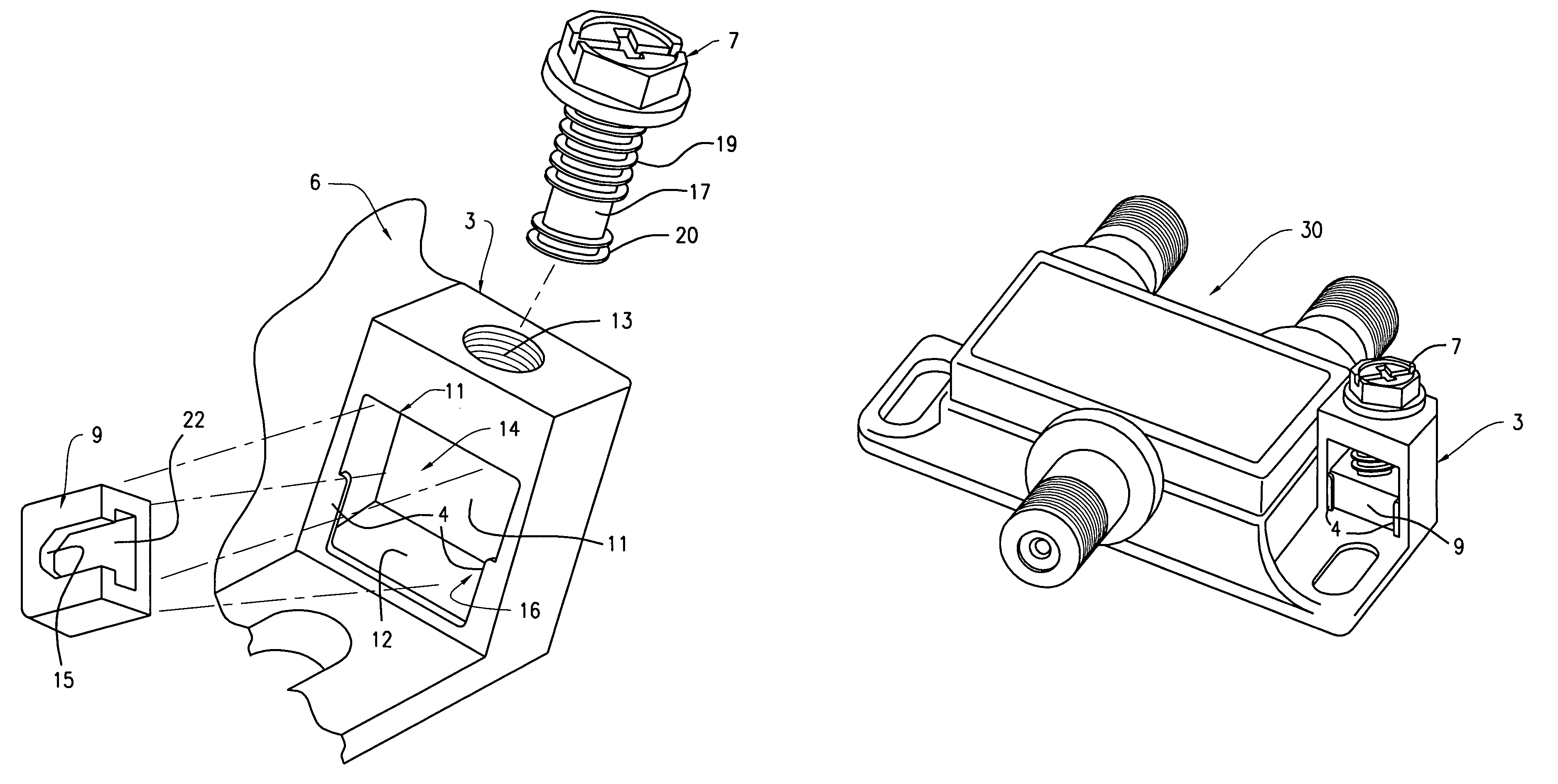
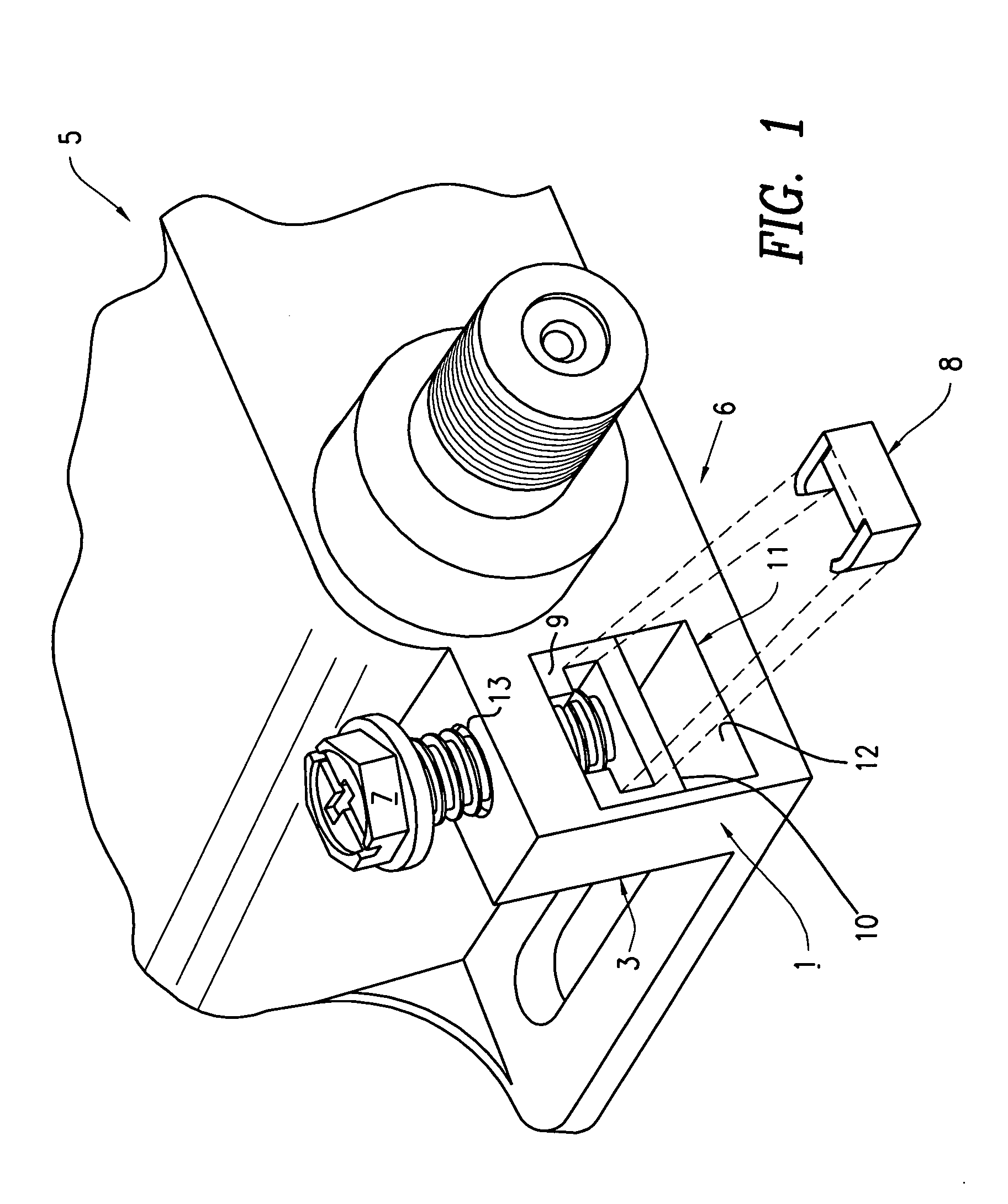
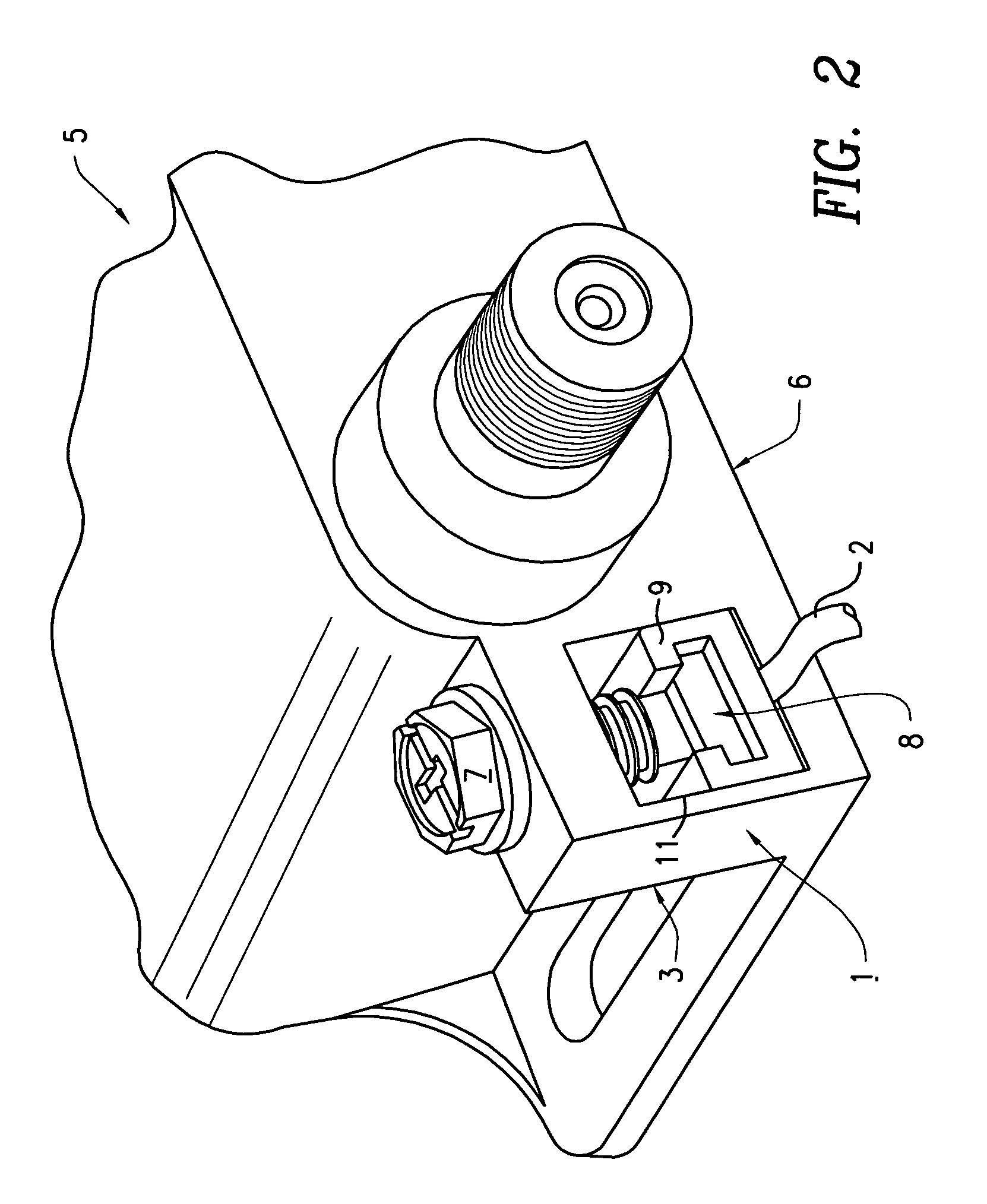
[0013]The present invention provides a ground block connection that can be used with cable television devices, and other electrical devices, particularly those associated with housings for enclosing various electrical components. However, the invention is not meant to be so limited, and can in certain embodiments be used to provide a stand alone ground block connector, for example. With reference to FIGS. 1 through 4, in one embodiment of the invention, the ground block connector 1 is retained in a sidewall protrusion 3 from the main housing 6 of a cable television device 5, such as an amplifier or splitter, or from housings for other electrical devices, for example.

[0014]The ground connector block 1 is formed in an electrically conductive protrusion 3 from a housing 6 of an electrical device 5, in this example. More specifically as shown in FIG. 1, the ground connection connector block 1 includes a compression bolt or screw 7 that is rotated in one direction for moving a compressio...


PUM


Abstract

A ground block connector is provided by forming a slot in a protrusion of a housing for an electrical device. A compression bolt is screwed into a threaded hole in the protrusion into the slot, for captively retaining a U-shaped compression electrical contact in the slot, whereby movement of the screw in one direction moves the contact toward the bottom of the slot, for compressibly retaining an end of a ground wire between the bottom of the contact and bottom of the slot.

Description

RELATED APPLICATION[0001]This Application is related to Ser. No. 60 / 603,146, filed Aug. 20, 2004, now abandoned for “Ground Block Connector,” and takes priority therefrom. The teachings of the co-pending Application are incorporated herein to the extent they do not conflict herewith.FIELD OF THE INVENTION[0002]The present invention relates generally to the electrical connectors, and more particularly to connectors for receiving a ground cable or wire.BACKGROUND OF THE INVENTION[0003]It is important in providing ground connections to housings of electrical devices, between devices, and to other typical electrical installations, that the connectors used permit easy, efficient, and reliable connection to ground wire or cable terminations. Known connectors are prone to damage the bared ends of ground wires or cables, and as such require care in use. There is a need in the art for connectors that permit rapid and easy connection to ground wires or cables, while substantially avoiding dam...

Claims


Application Information

Patent Timeline
Patent Type & Authority Patents(United States)
IPC IPC(8): H01R13/648
CPCH01R4/363
Inventor SHAPSON, JAY F.DYCK, ARTHUR
Owner TIMES FIBER COMMUNICATIONS INC
Why Eureka
Try Eureka