Bandsaw blade with cutting extensions

a bandsaw blade and cutting edge technology, applied in the field of bandsaw blades, can solve the problems of bandsaw blade wear, exhaustion of the useful life of the cutting edge, and disadvantages in the distribution of cutting load

Inactive Publication Date: 2006-05-02
GENENCOR INT INC
View PDF31 Cites 35 Cited by
  • Summary
  • Abstract
  • Description
  • Claims
  • Application Information

AI Technical Summary

Benefits of technology

[0012]These needs, and others, are met by the disclosed invention which provides a bandsaw blade having un-set teeth, each tooth having a cutting extension. The cutting extension extends beyond the height of the tooth body. Ad individual cutting extension has a width less than the width of the tooth body, but the total width of the cutting extensions in a group of teeth is the same as, or greater th...

Problems solved by technology

Both of these means of distributing the cutting load suffer from disadvantages.
This stress causes the bandsaw blade to wear out before the useful life of the cutting edges is exhausted.
Unset teeth having different heights may experience...

Method used


Image

  • Bandsaw blade with cutting extensions
  • Bandsaw blade with cutting extensions
  • Bandsaw blade with cutting extensions

Examples


Embodiment Construction

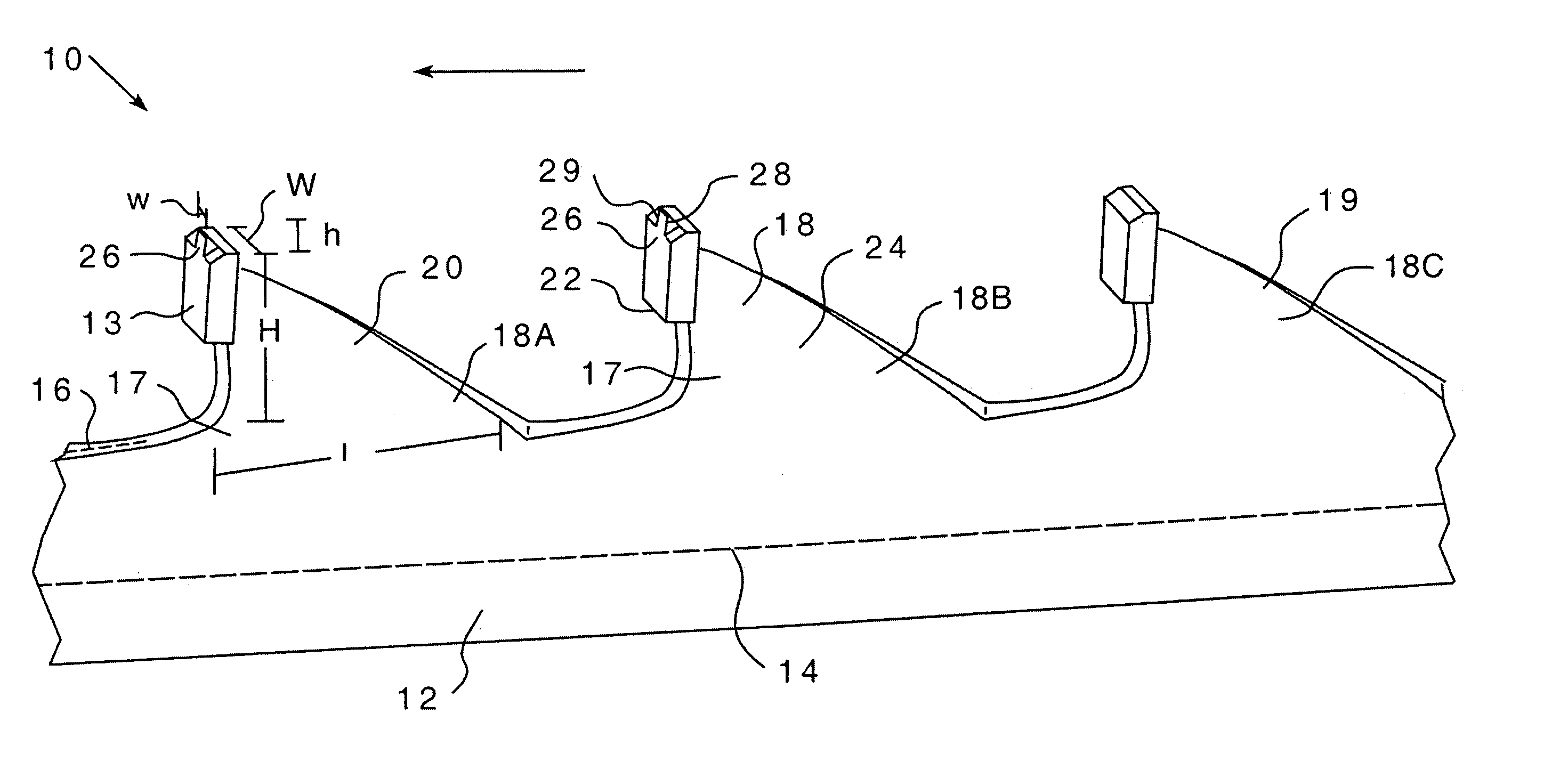
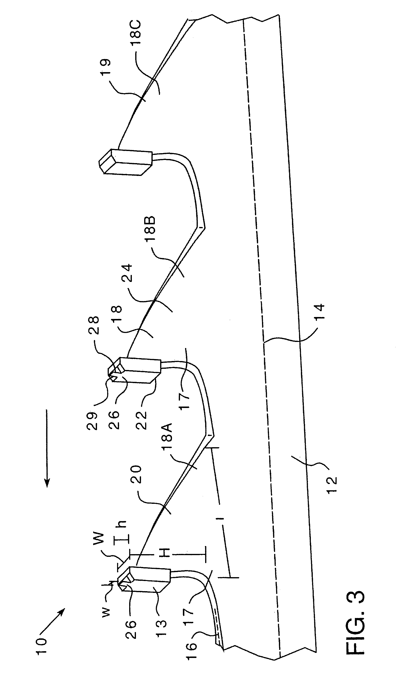
[0035]As shown in FIG. 3 a bandsaw blade 10 includes an elongated body 12 having a longitudinal axis 14, a center line 16, and a plurality of unset teeth 18 extending therefrom. The bandsaw blade 10 travels in a cutting path indicated by the arrow. As will be described fully below, the teeth 18A, 18B are disposed in repeating groups along the elongated body 12. The bandsaw body 12 is, typically, made from a metal such as steel. A carbide tip 13 having a cutting edge is usually attached to the bandsaw body 12 at the end of each tooth. However, as the bandsaw body 12 may have integral cutting edge, the carbide tip 13 shall hereinafter be described as part of a tooth body 20. Each tooth body 20 extends from the blade body 12. Each tooth body 20 has a height, identified by the letter “H”, a length, “L” and a width “W”. The tooth body 20 height and width are shown more clearly in FIGS. 6A–6C, described below. A tooth 18A, 18B is preferably between about 0.05 and 0.20 inches wide. The wid...


PUM

PropertyMeasurementUnit
Widthaaaaaaaaaa

Abstract

A saw blade that includes a bandsaw body and a plurality of unset teeth having a generally uniform height. The teeth are disposed on the bandsaw body. At least some of the teeth have a cutting extension that extends above the uniform height of the teeth.

Description

BACKGROUND OF THE INVENTION[0001]1. Field of the Invention[0002]This invention relates to a bandsaw blade and, more specifically, to a bandsaw having teeth with bodies of a generally uniform height and wherein at least some of the teeth have a cutting extension extending above the height of the teeth.[0003]2. Background Information[0004]Bandsaw blades include a flat body having a plurality of teeth extending therefrom. Each tooth has a height, extending above the body, a width, which is perpendicular to the longitudinal axis of the body, and a length, extending along the longitudinal axis of the body. Typically, the bandsaw body is made from a material such as steel and a carbide tip, which includes the cutting edge, is coupled to the tip of each tooth. The bandsaw blade moves in the longitudinal direction of the body in a single direction, hereinafter “the cutting path.” Each tooth also has a cutting edge located, generally, at the greatest height on the tooth. As the moving bandsa...

Claims


Application Information

Patent Timeline
IPC IPC(8): B27B33/02B23D61/12B23D61/14B27B33/06
CPCB23D61/121B27B33/06B23D61/14Y10T83/9346Y10T83/9348Y10T83/935Y10T83/9355Y10T83/9358
Inventor ALTON, WILLIAM GEORGE
Owner GENENCOR INT INC
Why Eureka
Try Eureka