Power steering system

Active Publication Date: 2006-05-02
HITACHI ASTEMO LTD
View PDF7 Cites 1 Cited by
  • Summary
  • Abstract
  • Description
  • Claims
  • Application Information

AI Technical Summary

Benefits of technology

[0006]It is, therefore, an object of the present invention to provide a power steering system for a motor vehicle, which allows sufficient relief of stress concentration at

Problems solved by technology

With the typical power steering system, however, due to the cylinder sleeve being thin, the R-shape of the connecting corner cannot be formed with sufficiently large radius of curvature, raising a prob

Method used


Image

  • Power steering system
  • Power steering system
  • Power steering system

Examples


Embodiment Construction

[0015]Referring to the drawings, a description is made about an embodiment of a power steering system for a motor vehicle according to the present invention.

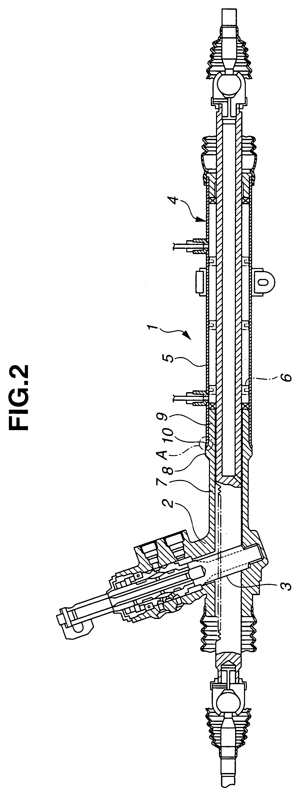
[0016]Referring to FIG. 2, a power steering system 1 comprises a gear housing 2 for accommodating a rack-and-pinion or steering-force transmitting gear 3, and an assisting power cylinder 4 connected to gear housing 2. Power cylinder 4 comprises a cylinder sleeve 5 which forms a cylinder main body and a piston rod 6 accommodated therein and operated hydraulically to move forward and backward. Piston rod 6 has one end integrated with the rack of rack-and-pinion 3.

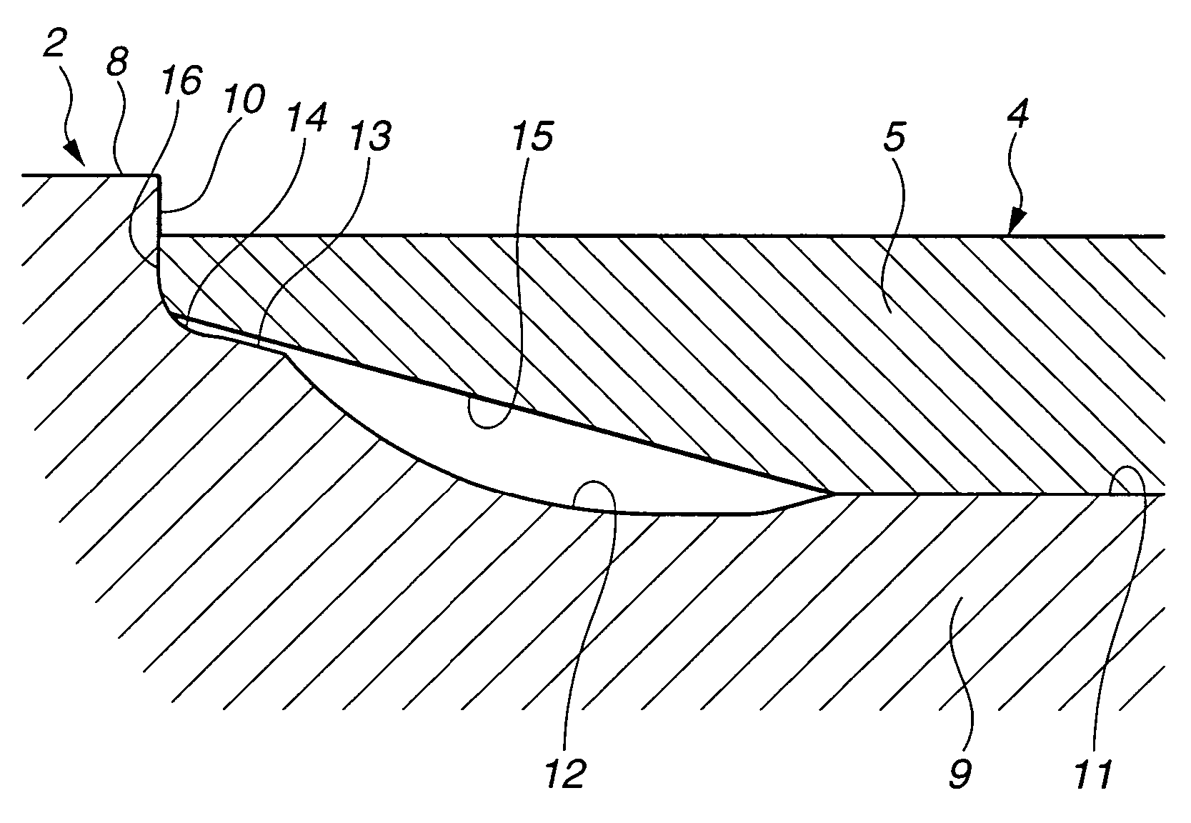
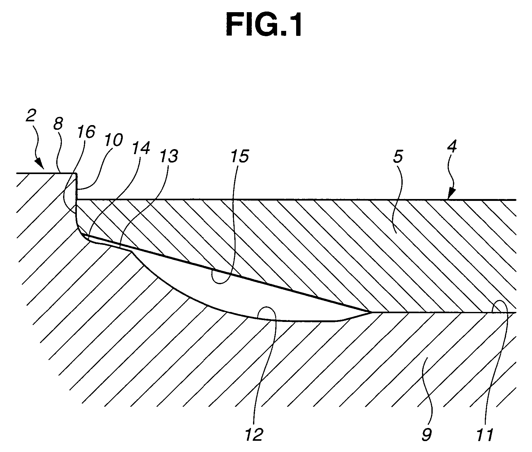
[0017]A rack guide 7 is arranged to extend from gear housing 2 so as to accommodate the rack of rack-and-pinion 3, and has at the front end a thick swelling 8 and a cylindrical wall 9 having reduced diameter with respect thereto, which are formed continuously. Referring also to FIG. 1, a butt wall 10 is arranged between swelling 8 and cylindrical wall 9 to be orthogonal t...


PUM


Abstract

A power steering system includes a first R-shaped portion formed with a cylindrical wall and curvedly extending from an outer-periphery general face of the cylindrical wall to the outer periphery of a butt wall, and a second R-shaped portion formed with the cylindrical wall and arranged between the butt wall and the first R-shaped portion, wherein the second R-shaped portion is smaller in radius of curvature than the first R-shaped portion.

Description

BACKGROUND OF THE INVENTION[0001]The present invention relates generally to a power steering system for a motor vehicle, and more particularly, to its improvement in a connection between a gear housing for accommodating a steering-force transmitting gear and a cylinder sleeve of a assisting power cylinder.[0002]As disclosed in JP-U 6-22156, a typical power steering system for a motor vehicle comprises a cylinder sleeve of a power cylinder connected to a gear housing for accommodating a steering-force transmitting gear such as a rack-and-pinion.[0003]In the power steering system, a cylindrical wall and a butt wall substantially orthogonal thereto are provided to a connection of the gear housing with the power cylinder. The cylinder sleeve is engaged on the outer periphery of the cylindrical wall to have a front-end face abutting on the butt wall. At an engagement of the cylinder wall and the cylinder sleeve, a connecting corner between the cylindrical wall and the butt wall often und...

Claims


Application Information

Patent Timeline
IPC IPC(8): B62D5/06B62D5/22F15B15/14B62D5/12
CPCF15B15/1438B62D5/22
Inventor MARUYAMA, TATSUYOSHIKANEKO, TAKAHIDE
Owner HITACHI ASTEMO LTD
Why Eureka
Try Eureka