Electromagnetic wave resistivity tool

a resistivity tool and electromagnetic wave technology, applied in instruments, borehole/well accessories, surveys, etc., can solve the problems of limited space within which to run wires and place circuits in downhole tools

Inactive Publication Date: 2006-05-02
HALLIBURTON ENERGY SERVICES INC
View PDF9 Cites 59 Cited by
  • Summary
  • Abstract
  • Description
  • Claims
  • Application Information

AI Technical Summary

Problems solved by technology

Moreover, the space within which to run wires and place circuits in a downhole tool is limited.
These factors militate against an LWD tool designer increasing functionality of transmitting antennas by adding circuits and power consuming components.

Method used


Image

  • Electromagnetic wave resistivity tool
  • Electromagnetic wave resistivity tool
  • Electromagnetic wave resistivity tool

Examples


Embodiment Construction

[0010]The problems noted above are solved in large part by a method and related system of an electromagnetic wave resistivity tool. One exemplary embodiment is a method that comprises operating a logging tool in a borehole (the logging tool having a transmitting antenna), transmitting from the transmitting antenna an electromagnetic wave having a first frequency, transmitting an electromagnetic wave having a second frequency, and transmitting an electromagnetic wave having a third frequency.

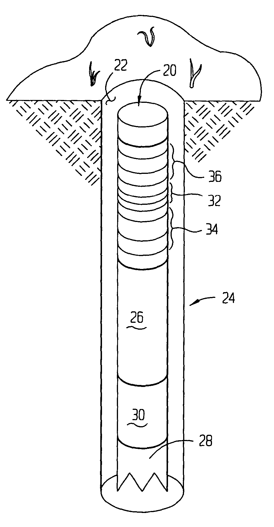
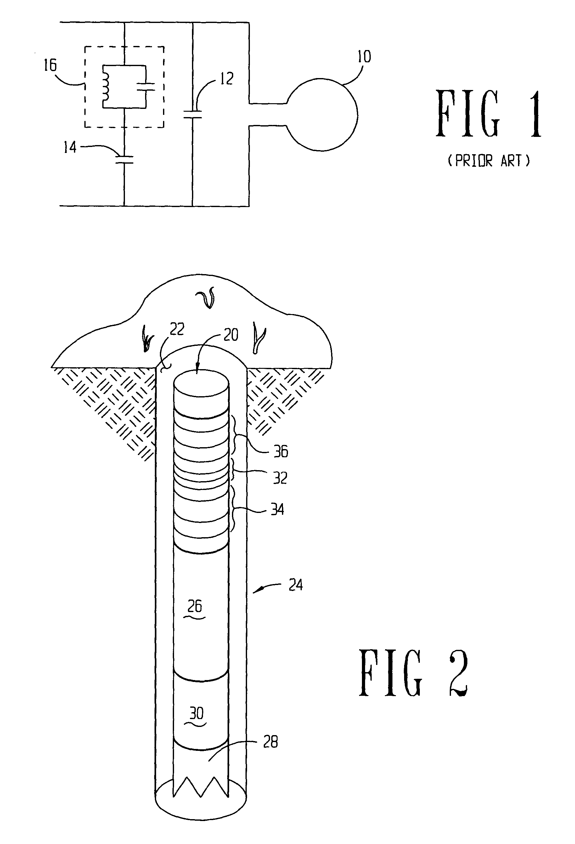
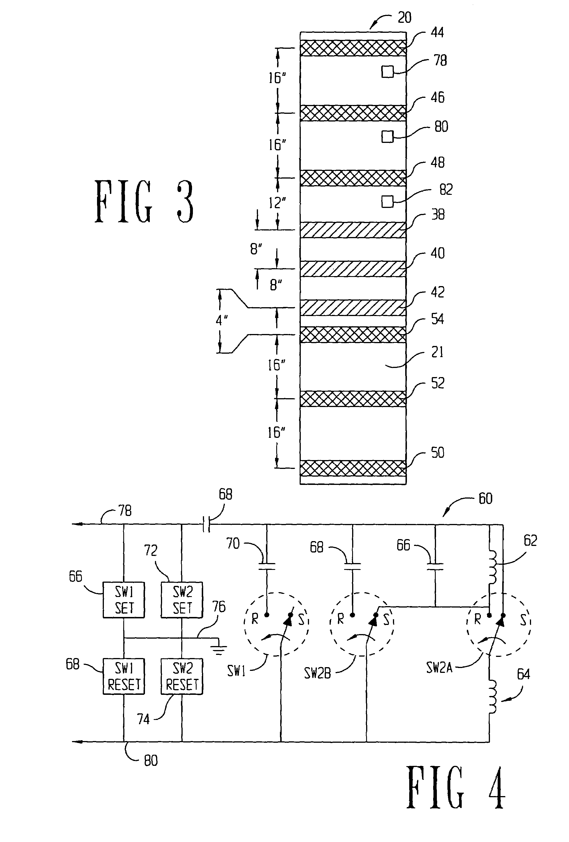
[0011]Another exemplary aspect may be a logging tool comprising a tool body adapted for use in a borehole, a receiving antenna disposed on a tool body, and a transmitting antenna disposed on the tool body at a spaced-apart location from the receiving antenna. The transmitting antenna may be selected with operable at three or more resonant frequencies for transmitting electromagnetic waves or electromagnetic radiation.

[0012]Yet another alternative embodiment may be a bottomhole assembly comprising...


PUM


Abstract

A method and system of operating an electromagnetic resistivity tool wherein at least one transmitting antenna of the tool is selectively operable at three or more resonant frequencies for better resistivity profiling of a formation.

Description

CROSS-REFERENCE TO RELATED APPLICATIONS[0001]None.STATEMENT REGARDING FEDERALLY SPONSORED RESEARCH OR DEVELOPMENT[0002]Not applicable.BACKGROUND OF THE INVENTION[0003]1. Field of the Invention[0004]The preferred embodiments of the present invention are directed to logging-while-drilling (LWD) electromagnetic wave tools. More particularly, embodiments of the invention are directed to multiple frequency LWD resistivity tools. More particularly still, embodiments of the invention are directed to LWD resistivity tools where at least one of the transmitting antennas may operate at three or more frequencies.[0005]2. Background of the Invention[0006]Wireline logging tools may be used to gather information regarding downhole formations. One such wireline logging tool is an induction resistivity tool for determining resistivity of the downhole formation. Resistivity may be determined at multiple depths of investigation, where the depth of investigation in a wireline tool operating at a low f...

Claims


Application Information

Patent Timeline
Patent Type & Authority Patents(United States)
IPC IPC(8): G01V3/18G01V3/30
CPCG01V3/28G01V3/30
Inventor BESTE, RANDAL T.GOLLA, CHRISTOPHER A.BITTAR, MICHAEL
Owner HALLIBURTON ENERGY SERVICES INC
Why Eureka
Try Eureka