Method to smooth photometric variations across multi-projector displays

Inactive Publication Date: 2006-05-02
UCHICAGO ARGONNE LLC +1
View PDF11 Cites 61 Cited by
  • Summary
  • Abstract
  • Description
  • Claims
  • Application Information

AI Technical Summary

Benefits of technology

[0023]In accordance with features of the invention, in the photometric calibration step a digital camera is used to measure the color response of the multi-projector display. Using the generated luminance attenuation map (LAM) for each projector for image correction in real time smoothes out distracting color variations across the multi-projector display while maximizing a perceived dynamic range of the display. Initial calibration operations includ

Problems solved by technology

A difficulty with many of the multi-projector display systems is that the multiple images often do not appear as one single continuous image on the display screen.
When multi

Method used


Image

  • Method to smooth photometric variations across multi-projector displays
  • Method to smooth photometric variations across multi-projector displays
  • Method to smooth photometric variations across multi-projector displays

Examples


Embodiment Construction

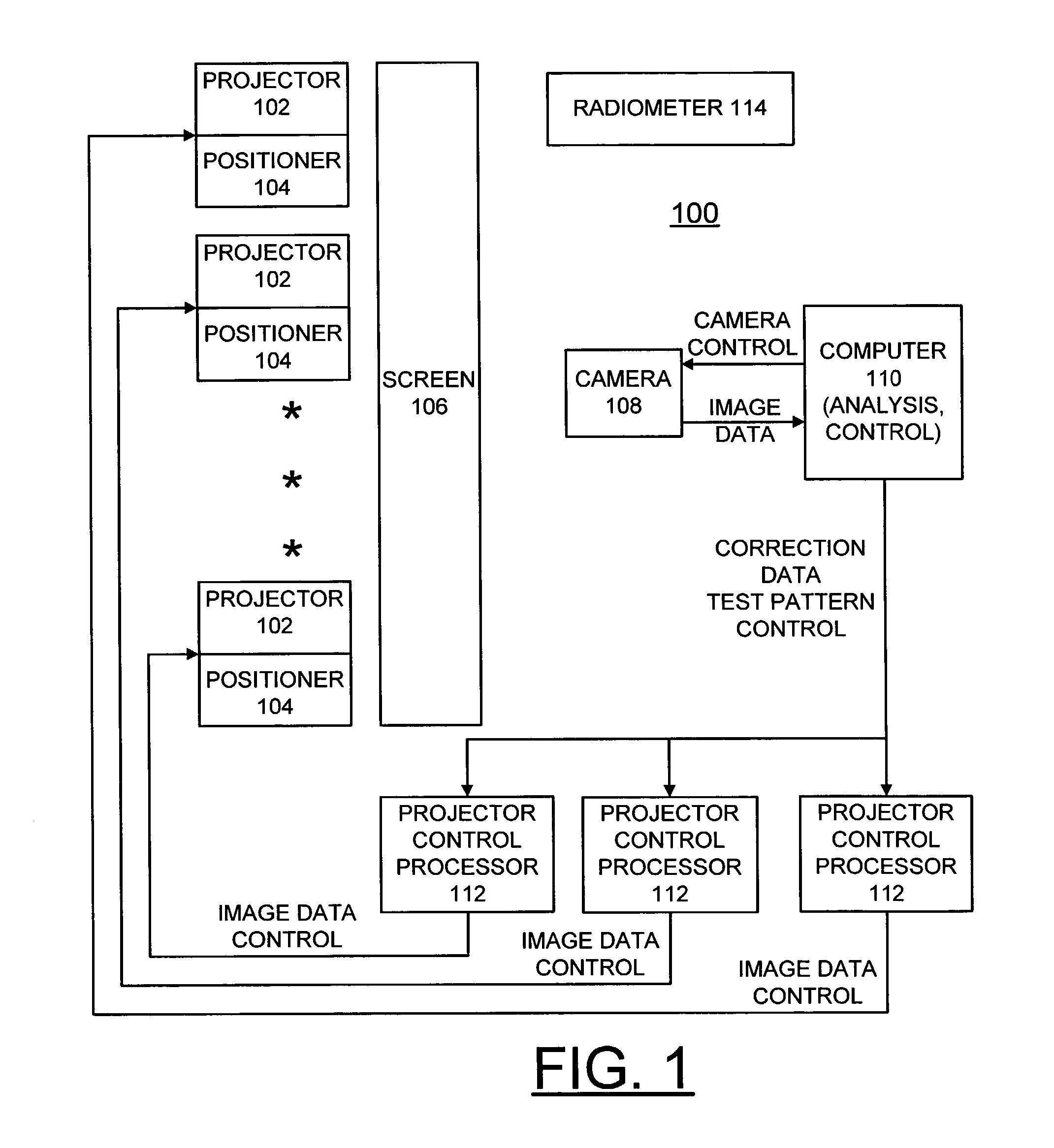
[0026]Having reference now to the drawings, in FIG. 1 there is shown a multi-projector display system generally designated by the reference character 100 for implementing the novel method to smooth photometric variations across multi-projector displays in accordance with the preferred embodiment. Multi-projector display system 100 includes a plurality of projectors 102, each having an associated positioner 104, for projecting large area, high resolution tiled displays onto a display screen 106. Multi-projector display system 100 includes an array of multiple projectors 102, for example, a 3×5 array of 15 projectors 102. Multi-projector display system 100 includes a camera 108 for capturing tiled display images and applying image data to a computer 110 for analysis and implementing the method to smooth photometric variations across multi-projector displays in accordance with the preferred embodiment. Computer 110 optionally operatively controls camera 108 as indicated at a line label...


PUM


Abstract

A method is provided to smooth photometric variations across multi-projector displays. Photometric calibration is performed to generate a luminance attenuation map (LAM) for each projector. An image for each projector is modified using the luminance attenuation map (LAM) for each projector to provide image correction in real time. In the photometric calibration step a digital camera is used to measure the color response of the multi-projector display. Using the generated luminance attenuation map (LAM) for each projector for image correction in real time smoothes out distracting color variations across the multi-projector display while maximizing a perceived dynamic range of the display.

Description

CONTRACTUAL ORIGIN OF THE INVENTION[0001]The United States Government has rights in this invention pursuant to Contract No. W-31-109-ENG-38 between the United States Government and Argonne National Laboratory.RELATED APPLICATION[0002]A related U.S. patent application Ser. No. 10 / 283,719, entitled “METHODS AND MEASUREMENT ENGINE FOR ALIGNING MULTI-PROJECTOR DISPLAY SYSTEMS” by Mark Hereld, Ivan Judson and Rick Stevens and assigned to the present assignee, is being filed on the same day as the present patent application.[0003]1. Field of the Invention[0004]The present invention relates to a method to smooth photometric variations across multi-projector displays.[0005]2. Description of the Related Art[0006]Tiled projection display systems use multiple projectors to produce a large, high-resolution image. In many known systems, multiple screens are placed next to each other to form a large image display. A difficulty with many of the multi-projector display systems is that the multiple ...

Claims


Application Information

Patent Timeline
IPC IPC(8): H04N5/66H04N5/74H04N9/12H04N17/00
CPCH04N9/12H04N9/3194H04N9/3185H04N9/3147
Inventor MAJUMDER, ADITISTEVENS, RICK L.
Owner UCHICAGO ARGONNE LLC
Why Eureka
Try Eureka