
Display device and method for expanding color space

a color space and display device technology, applied in the field of display devices, can solve the problems of low light use efficiency, achieve the effect of smooth color variation, and increase in ic size and cos

Active Publication Date: 2018-12-06
SHARP KK
View PDF3 Cites 2 Cited by
  • Summary
  • Abstract
  • Description
  • Claims
  • Application Information

AI Technical Summary

Benefits of technology

The present invention provides a display device that can expand its color space without increasing the size or cost of the device. The device uses an inverse of saturation as its expansion coefficient, which allows for smooth color variation and prevents a great change in the expansion coefficient value between adjacent pixels. The device can also produce a white display and effectively expand its color space. Additionally, the device employs a color filter system and also capable of expanding its color space without increasing its size or cost.

Problems solved by technology

Further, since the liquid crystal display device employing a color filter system as described above has the problem of having low light use efficiency, a liquid crystal display device employing a field-sequential color system in which a color display is produced without using color filters has also become widespread.

Method used


Image

  • Display device and method for expanding color space
  • Display device and method for expanding color space
  • Display device and method for expanding color space

Examples


first embodiment

1. First Embodiment

[0075]

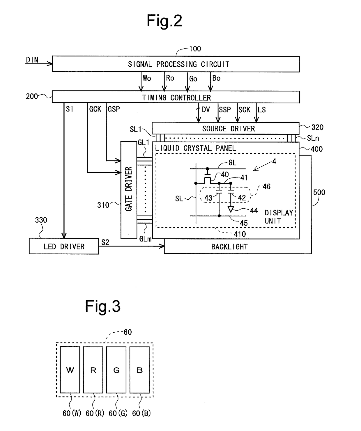
[0076]FIG. 2 is a block diagram showing an overall configuration of a liquid crystal display device according to a first embodiment of the present invention. This liquid crystal display device includes a signal processing circuit 100, a timing controller 200, a gate driver 310, a source driver 320, an LED driver 330, a liquid crystal panel 400, and a backlight 500. The gate driver 310 or the source driver 320, or both of those drivers, may be provided in the liquid crystal panel 400. The liquid crystal panel 400 includes a display unit 410 for displaying an image. In the present embodiment, it is assumed that the backlight 500 is configured by a red LED, a green LED, and a blue LED.

[0077]As for FIG. 2 a plurality of (n) source bus lines (video signal lines) SL1 to SLn and a plurality of (m) gate bus lines (scanning signal lines) GL1 to GLm are disposed in the display unit 410. A pixel formation portion 4 which forms a pixel (sub pixel) provided at a correspo...

second embodiment

2. Second Embodiment

[0107]

[0108]In the above first embodiment, the expansion coefficient E for a certain pixel (hereinafter referred to as a “target pixel”) is decided based only on a value of an input video signal for the target pixel. However, in a case in which the expansion coefficient E is decided in this manner, at the time of the expansion coefficients E being greatly different between adjacent pixels, color variation concerning the display image may not be smooth. Hence, in the present embodiment, the configuration capable of obtaining a display image with smooth color variation is adopted. It should be noted that, since the overall configuration and the configuration of the signal processing circuit 100 are the same as those of the first embodiment described above, the descriptions thereof are omitted (see FIGS. 1 to 3).

[0109]

[0110]In the above first embodiment, the expansion coefficient E for the target pixel is decided based on the signal value of the j put video signal f...

third embodiment

3. Third Embodiment

[0115]

[0116]In each of the above first and second embodiments, the description has been given by taking the liquid crystal display device employing the color filter system as an example. However, the present invention is not limited thereto. So, an example where a liquid crystal display device employing a field-sequential color system is adopted will be described as a third embodiment of the present invention.

[0117]FIG. 10 is a diagram showing a configuration of one frame period in the present embodiment. As shown in FIG. 10, one frame period is temporally divided into a white field for displaying a white screen, a red field for displaying a red screen, a green field for displaying a green screen, and a blue field for displaying a blue screen. In the white field, the red LED, the green LED, and the blue LED come into a lighting state after the lapse of a predetermined period from a field starting point.

[0118]In the red field, the red LED comes into the lighting st...


PUM


Abstract

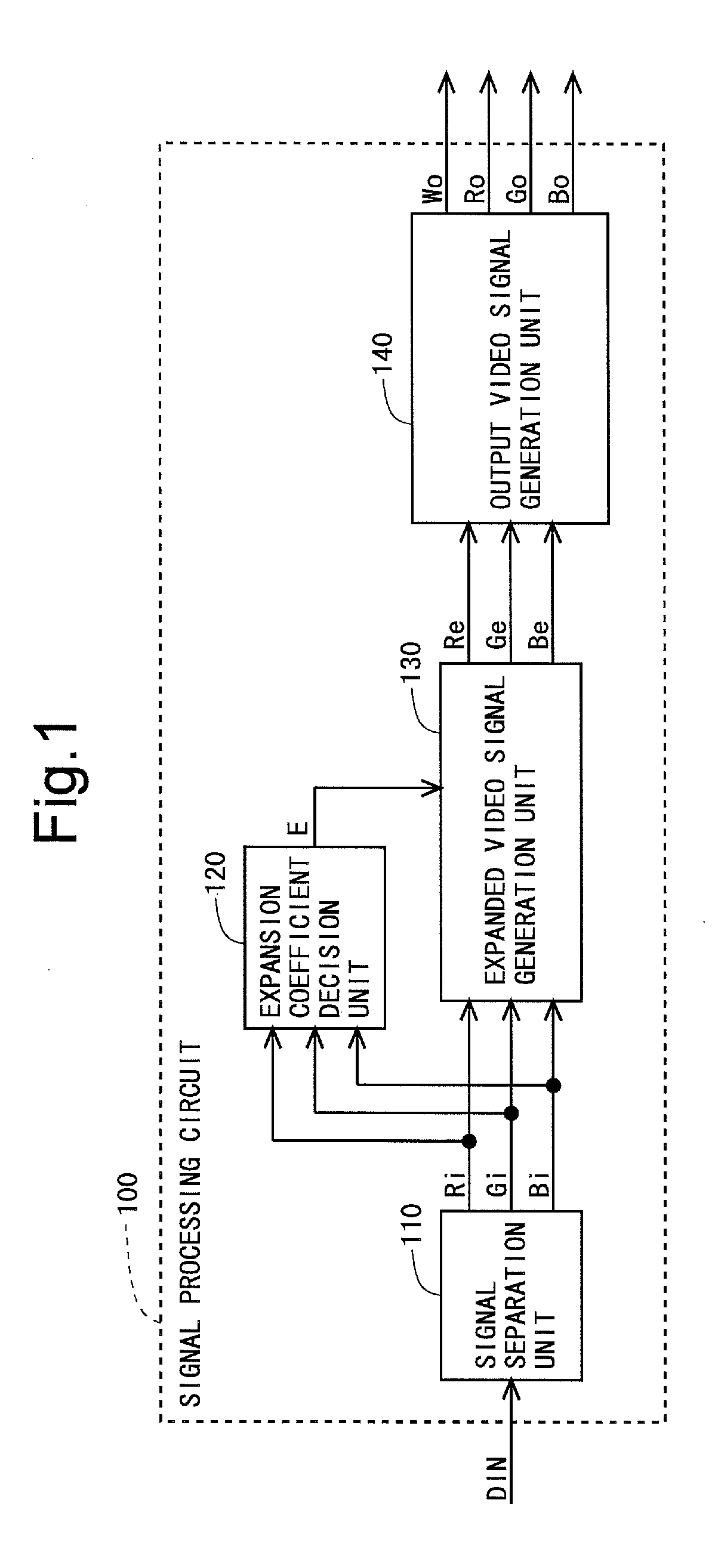
Provided is a display device capable of expanding a color space without causing an increase in IC size and cost.A signal processing circuit (100) is provided with: a signal separation unit (110) configured to separate an input video signal into components of individual colors; an expanded video signal generation unit (130) configured to perform an expansion process for increasing a signal value of the input video signal, and output data obtained by the expansion process as an expanded video signal; an expansion coefficient decision unit (120) configured to decide an expansion coefficient E to be used for the expansion process; and an output video signal generation unit (140) configured to generate an output video signal to be outputted to the display panel based on the expanded video signal. The expansion coefficient decision unit (120) decides an inverse of saturation, obtained based on the input video signal, as the expansion coefficient E for each pixel.

Description

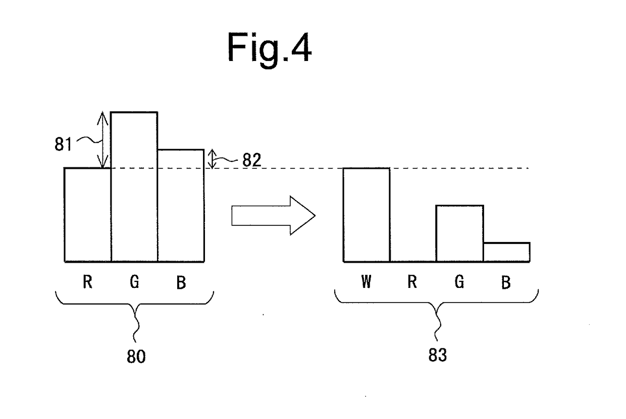
TECHNICAL FIELD[0001]The present invention relates to a display device, and more specifically relates to a display device that expands a color space by displaying white in addition to the three primary colors.BACKGROUND ART[0002]Generally, in a liquid crystal display device for producing a color display, one pixel is divided into three sub pixels: a red sub pixel provided with a color filter that transmits red light, a green sub pixel provided with a color filter that transmits green light, and a blue sub pixel provided with a color filter that transmits blue light. The color display can be produced by the color filters provided in these three sub pixels. However, in recent years, for the purpose of expanding a color space (a color gamut or a color reproduction range), there has also been developed a liquid crystal display device in which one pixel includes a white sub pixel that transmits white light, and the above three sub pixels (i.e., a liquid crystal display device in which on...

Claims


Application Information

Patent Timeline
Patent Type & Authority Applications(United States)
IPC IPC(8): G09G3/20G09G3/36
CPCG09G3/2003G09G3/3607G09G2340/06G09G2330/021G09G2310/0235G09G3/005G09G3/3648G09G3/20G09G3/36
Inventor KOIZUMI, RYOHEI
Owner SHARP KK
Learn More