Double pulsating hydrotherapy jet

a technology of hydrotherapy jets and pulsating jets, which is applied in the field of hydrotherapy jets, can solve the problems of increasing system cost and adding complexity, requiring additional components, and abrupt pressure increases imposing strain on spa systems

Inactive Publication Date: 2006-05-16
B&S PLASTICS
View PDF8 Cites 18 Cited by
  • Summary
  • Abstract
  • Description
  • Claims
  • Application Information

AI Technical Summary

Problems solved by technology

These systems have met with varying degrees of success as they often require additional or larger components, which increase system cost and add complexity, or generate unwanted pressure losses, thus requiring a larger pump than would otherwise be required.
While this approach does provide a pulsating effect, blocking and unblocking of the flow stream causes abrupt pressure increases imposing a strain on spa systems.
Aside from these drawbacks, such systems require additional components that add complexity, cost and weight.
In addition, since the pulsation effect is generated away from the jet, the pulsed flow stream experiences a pressure loss, resulting in a decreased pulsation effect being felt at the jet exit.
While hydraulic systems do provide a degree of pulsation, they too suffer from many of the same problems as mechanical systems.
For example, as the pulsation effect is generated away from the jet, the pulsed flow stream experiences a pressure loss which results in a reduced pulsation effect at the jet, and like the mechanical systems the additional componentry adds complexity, cost and weight to the system.
However, this is not truly a pulsed flow since the user actually experiences a continual flow stream, but in a circular pattern.
The blocking, however, creates an undesirable backflow into the jet, causing strain on the spa system and ultimately lowering efficiency.
In addition, the Spinnett design requires multiple deflections of the flow stream as it passes through the jet, causing pressure losses and lowering the system efficiency.

Method used


Image

  • Double pulsating hydrotherapy jet
  • Double pulsating hydrotherapy jet
  • Double pulsating hydrotherapy jet

Examples


Embodiment Construction

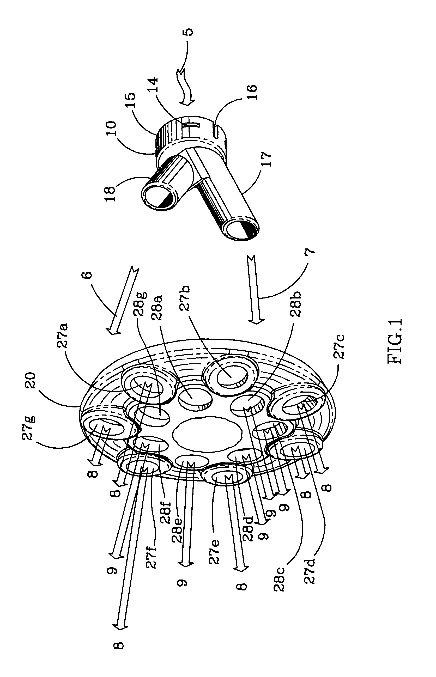
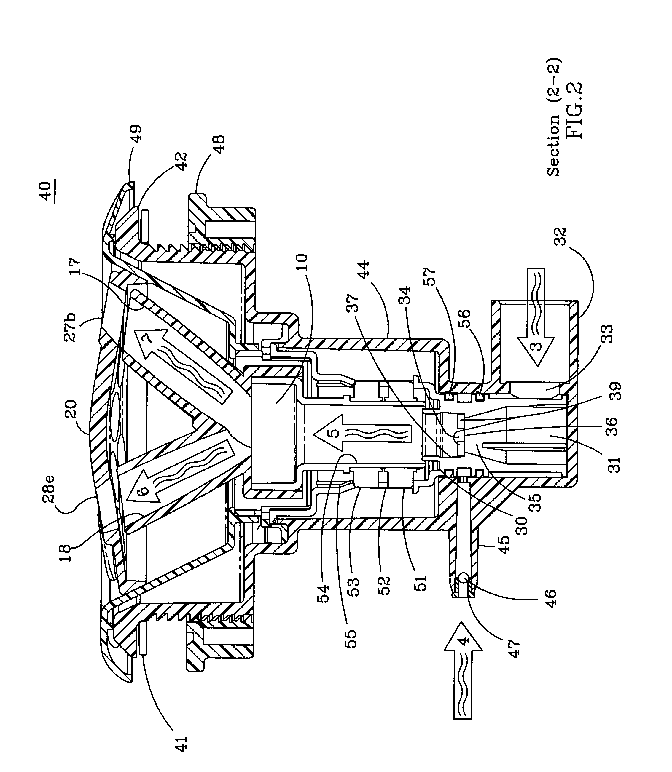
[0032]The invention, as shown in FIG. 1, relates to a low-pressure loss hydrotherapy jet system 40 that uses a single water supply 3 (not shown) and a single air intake 4 (not shown) to produce multiple concentric, rings of simultaneously pulsating water streams in a spa bath. As shown in FIG. 1 aerated water stream 5 enters discharge member 10, which has a major outlet conduit 17 and a minor outlet conduit 18. Water stream 5 enters discharge member 10 and splits into subsidiary streams 6 and 7, which exit discharge member 10 through minor outlet conduit 18 and major outlet conduit 17 respectively. Subsidiary streams 6 and 7 discharge in concentric patterns from discharge member 10. The subsidiary streams 6 and 7 impinge a concentric arrangement of openings 28a–28g and 27a–27g respectively disposed on cap 20. Subsidiary stream 7 passing through openings 27a–27g generates a ring of major pulsating streams 8. Subsidiary stream 6 passing through openings 28a–28g generates a ring of min...


PUM


Abstract

A pulsating hydrotherapy jet is disclosed which has a jet body with a water inlet to allow water to flow into the body. The jet body discharges the water through a discharge member in more than one concentric pattern. A cap mounted on the body to receive the circular water patterns is also disclosed. The cap has a number of openings that form more than one concentric opening ring. Each of the opening rings align with a respective one of the circular water patterns to provide the sensation of a number of circular patterns of multiple pulsating jets. A system for providing a hydrotherapy jet to a reservoir of water is also disclosed. The system includes a reservoir shell capable of holding water with a number of hydrotherapy jets according to the invention that are mounted around the reservoir shell. A water pump system circulates water from the reservoir to the jets.

Description

BACKGROUND OF THE INVENTION[0001]1. Field of the Invention[0002]This invention relates to hydrotherapy jets.[0003]2. Description of the Related Art[0004]Various hydrotherapy jets have been developed for use in spas, hot tubs, pools and bath tubs that discharge a stream of water that can be aerated through a variety of discharge nozzles. Designs of these hydrotherapy jets provide different flow characteristics that result in different massage effects being experienced by the body. Such jets have been found to produce a pleasing massage effect for many users, and have become quite popular. In the design of single or multi-use spas or tubs, it is common to use a variety of different jet nozzles to provide a variety of different massaging effects.[0005]Early jets simply discharged a stream of warm water along the longitudinal axis of the jet body, with later jets providing aeration of the water stream. Since then numerous jets have been developed in which the direction of the stream can...

Claims


Application Information

Patent Timeline
Patent Type & Authority Patents(United States)
IPC IPC(8): A61H33/00A61H33/02A61H33/04
CPCA61H33/027A61H33/6057A61H33/6063A61H2201/1238A61H2033/023
Inventor HOLTSNIDER, MICHAEL D.COLIN, RAYMUNDO
Owner B&S PLASTICS
Why Eureka
Try Eureka