
Group communication device and method
a communication device and group technology, applied in the field of group communication methods, can solve the problems of difficult to define a group, difficulty in defining which members can communicate with each other, and high cost, and achieve the effects of simple user interface design, simple appearance, and robust body
- Summary
- Abstract
- Description
- Claims
- Application Information
AI Technical Summary
Benefits of technology
Problems solved by technology
Method used
Image

Examples
Embodiment Construction
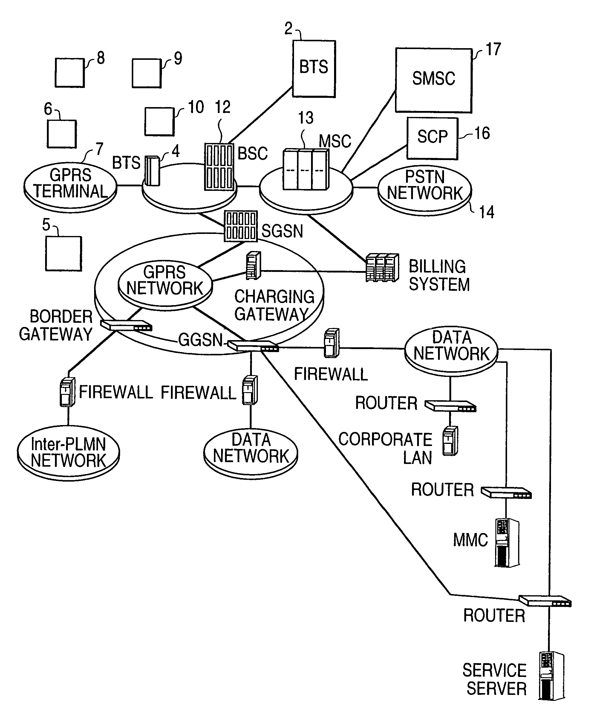
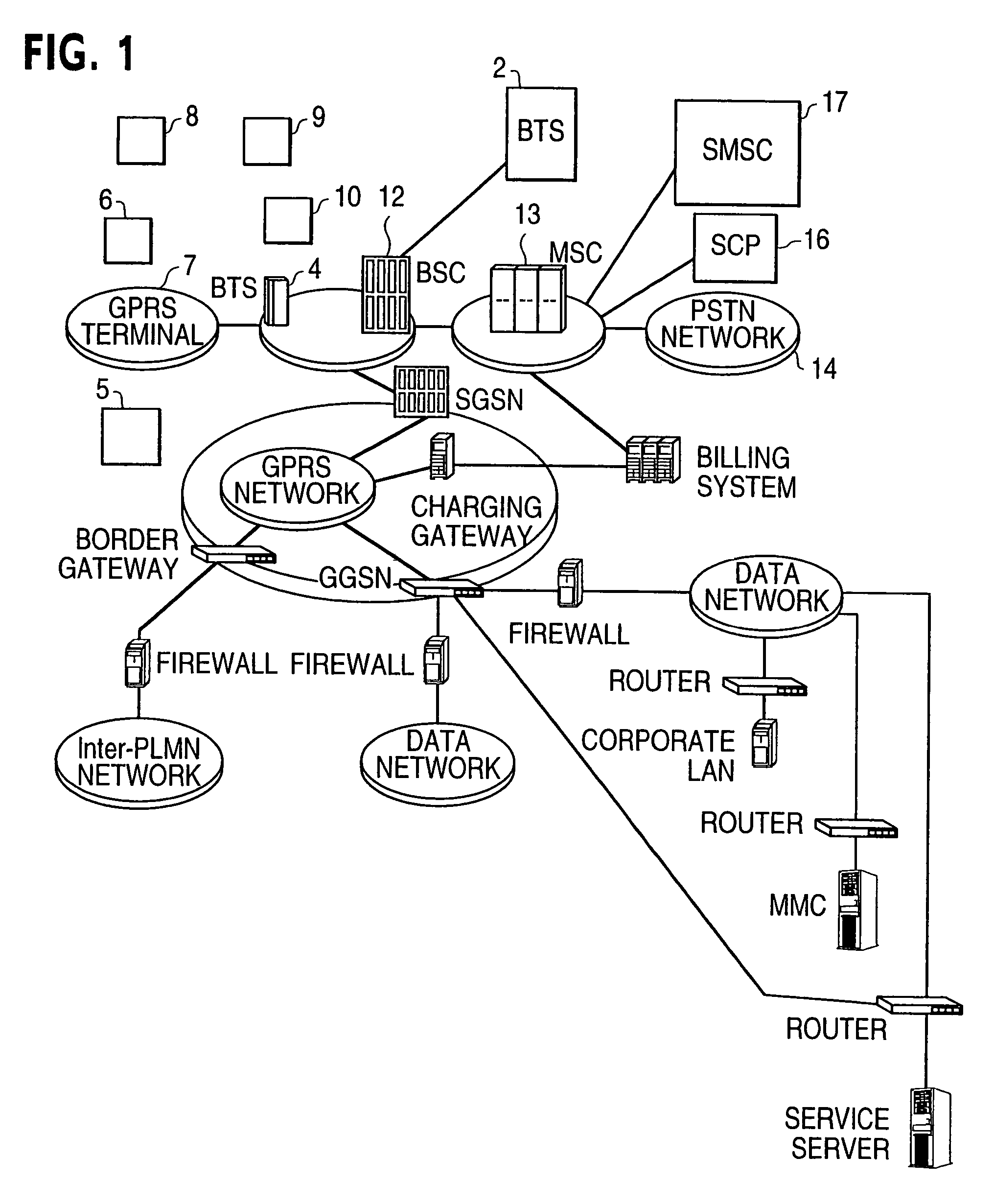
[0046]FIG. 1 shows both a circuit and switched telecommunications network. The network comprises a number of base stations (BTSs) 2, 4 etc. Each base station has a radio transceiver capable of transmitting radio signals to and receiving radio signals from the area of an associated cell. By means of these signals the base station can communicate with the mobile terminal 5, 6 in the associated cell, e.g. Nokia 2110. The terminals 7, 8, 9, 10 represent terminals according to the present invention and will be discussed in more detail later in this description. Each terminal includes a radio transceiver, respectively. Each base station 2, 4 is connected via a base station controller (BSC) 11, 12 to mobile switching center (MSC) 13 which is linked in turn to the public telephone network (PSTN) 14 to other mobile switching centers (not shown). The MSC is linked to service controlling point SCP 16 in order to reach the Intelligent network services. A short message service center (SMSC) 17 f...
PUM
 Abstract
Description
Claims
Application Information