Axial LED source

a technology of led source and axial led source, which is applied in the direction of fixed installation, lighting and heating apparatus, lighting support devices, etc., can solve the problems of reducing the flux the control of the shape of the desired pattern, and the inability to contribute to the desired pattern, so as to reduce the size of the source

Inactive Publication Date: 2006-05-23
LUMILEDS
View PDF21 Cites 189 Cited by
  • Summary
  • Abstract
  • Description
  • Claims
  • Application Information

AI Technical Summary

Problems solved by technology

However, a number of light rays do not strike reflector 106A and therefore do not contribute to the desired pattern.
This reduces the flux in the desired pattern and the control over the shape of the desired pattern.
Generally, it is difficult to create a pattern with a small spot size that has high candela values with a sharp cut off.
However, as the focal length becomes too small, it becomes difficult to align the focus of the reflector to the light source in the manufacturing process.

Method used


Image

  • Axial LED source
  • Axial LED source
  • Axial LED source

Examples


Embodiment Construction

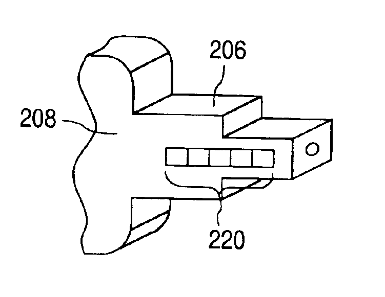
[0042]FIGS. 2A and 2B illustrate perspective views of a lamp 200 in the embodiments of the invention. Lamp 200 generates a far-field pattern 202 about a lamp axis 204. Lamp axis 204 is generally along the direction of light emission. Pattern 202 can be shaped for a variety of applications, including automotive, directional (e.g., similar to MR, AR, PAR projection lights), retail, hospitality, and commercial lighting.

[0043]Lamp 200 includes a base 208 (e.g., a socket) that can be plugged into an electrical receptacle to receive power and control signals. A post 206 extends from base 208 along lamp axis 204. Post 206 can be made in a variety of shapes (described later) to provide a number of post facets where one or more LED light sources are mounted. Post 206 includes the necessary electrical wiring for coupling the LED light sources to external power and control signals received at base 208.

[0044]Although only one LED source 210 is visible in FIG. 2A, any number of LED sources 210 c...


PUM


Abstract

A lamp has LED sources that are placed about a lamp axis in an axial arrangement. The lamp includes a post with post facets where the LED sources are mounted. The lamp includes a segmented reflector for guiding light from the LED sources. The segmented reflector includes reflective segments each of which is illuminated primarily by light from one of the post facets (e.g., one of the LED sources on the post facet). The LED sources may be made up of one or more LED dies. The LED dies may include optic-on-chip lenses to direct the light from each post facet to a corresponding reflective segment. The LED dies may be of different sizes and colors chosen to generate a particular far-field pattern.

Description

FIELD OF THE INVENTION[0001]This invention relates to light emitting diodes (“LEDs”) and in particular to lamps with multiple LED sources.DESCRIPTION OF RELATED ART[0002]FIG. 1A illustrates a conventional lamp 100A using a filament bulb 102A. Filament bulb 102A is located perpendicular to a lamp axis 104A in a trans-axial arrangement. Lamp axis 104A is an axis generally along the direction of light emission. A reflector 106A shapes (e.g., collimates) a number of light rays from bulb 102A to form a desired far-field pattern. However, a number of light rays do not strike reflector 106A and therefore do not contribute to the desired pattern. This reduces the flux in the desired pattern and the control over the shape of the desired pattern.[0003]FIG. 1B illustrates a conventional lamp 100B using a filament bulb 102B that is aligned with a lamp axis 104B in an axial arrangement. Due to the axial arrangement, a greater number of light rays strike reflector 106B and contribute to a desired...

Claims


Application Information

Patent Timeline
Patent Type & Authority Patents(United States)
IPC IPC(8): F21V7/00F21V29/00F21K99/00F21S2/00F21S8/04F21S8/10F21V5/04F21V7/09F21V13/00F21Y101/02H01L33/00H01L33/48H01L33/58H01L33/60
CPCF21K9/00F21S48/1159F21V7/09F21V29/77F21V29/006F21S48/1364F21S48/328F21Y2101/02F21Y2111/005F21Y2111/007F21V29/004F21Y2101/00F21Y2115/10F21Y2107/30F21Y2107/40F21K9/68F21S41/335F21S45/47F21V29/51F21S41/151F21S41/148
Inventor MARTIN, PAUL S.WEST, R. SCOTTSTEIGERWALD, DANIEL A.
Owner LUMILEDS
Why Eureka
Try Eureka