Camera actuator

a technology for actuating and cameras, applied in the field of cameras, can solve the problems of lack of ease of use of most of these devices

Inactive Publication Date: 2006-05-23
WINTRON TECH
View PDF5 Cites 11 Cited by
  • Summary
  • Abstract
  • Description
  • Claims
  • Application Information

AI Technical Summary

Problems solved by technology

Most of these devices lack ease of use when trying to move the camera to obtain a accurate view of the area in question, while at the same time allowing the user to observe what the camera is projecting on a display.

Method used


Image

  • Camera actuator
  • Camera actuator
  • Camera actuator

Examples


Embodiment Construction

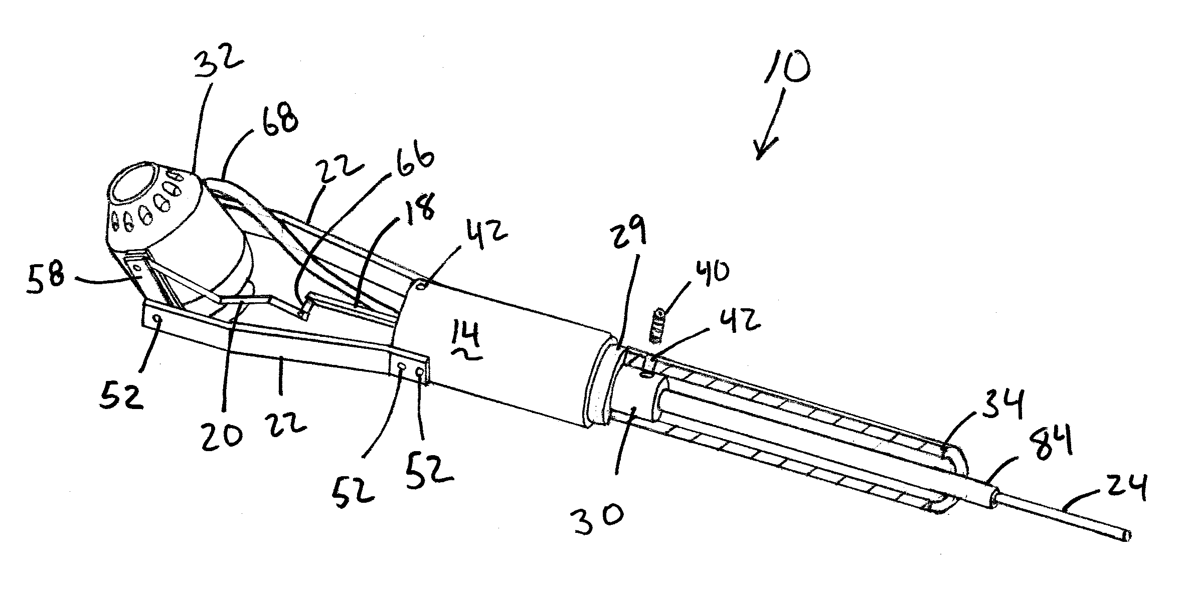
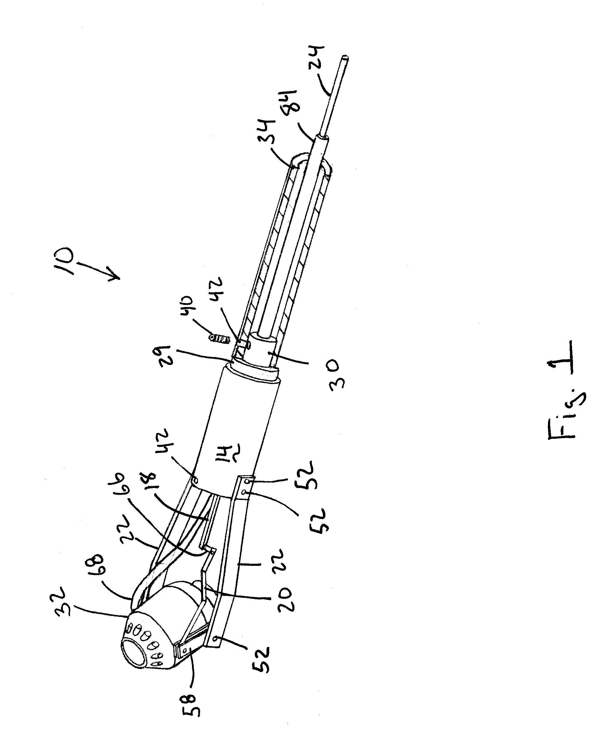
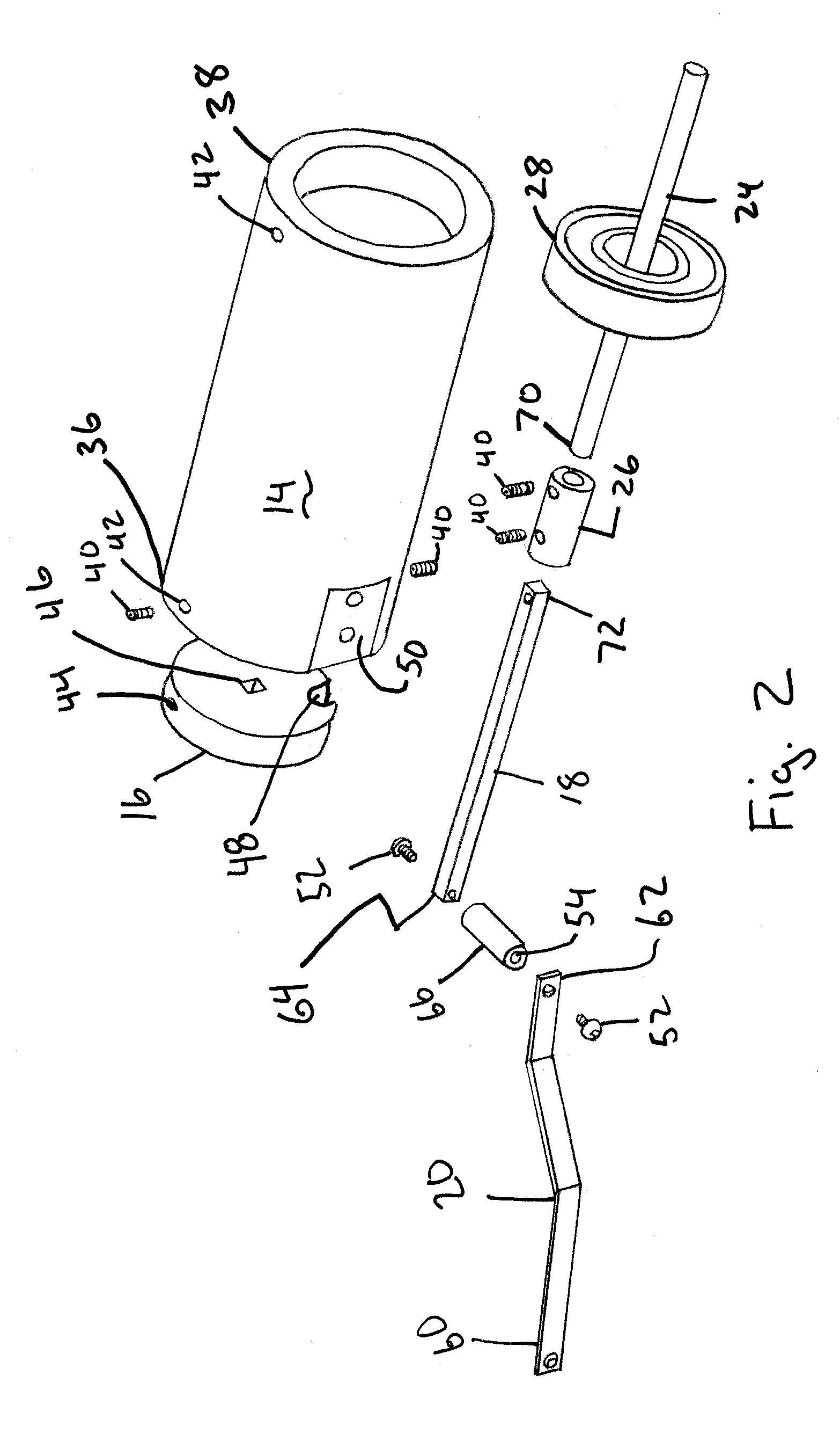
[0011]The present invention is a camera actuator 10, as shown in FIGS. 1–5. The camera actuator 10 is shown for mounting on a pole, but could be used in other applications. The camera actuator 10 is made up of several components, which include a main body 14, front cap 16, push arm 18, camera link 20, camera supports 22, actuator cable 24, coupler 26, rear bearing 28, felt ring 29 and rotation head 30. A camera 32 and pole 34 are also shown in FIG. 1.

[0012]The main body 14 is shown as a hollow open ended cylinder with a front end 36 and a rear end 38. The front cap 16 fits into the open end of the front end 36 of the main body 14. The front cap 16 is secured in the main body 14 using two set screws 40 which screw into set screw holes 42 and against the side 44 of the front cap 16. The front cap 16 includes a push arm hole 46 and a wire groove 48, as shown in FIG. 2. The push arm hole 46 is in the middle of the front cap 16. The main body 14 includes two mounting areas 50 milled into...


PUM


Abstract

A camera actuator having a main body, camera support, camera link, push arm and actuator cable. The main body rotatably mounts to a pole. The camera support extends from the front of the main body. The camera support is adapted to rotatably receive a camera. The camera link connects to the camera, where movement of the camera link moves the camera about the camera support. The push arm extends from the front of the main body and is connected to the camera link. The push arm mounts in the main body such that the push arm slides in and out of the front of the main body to rotate the camera. The push arm mounts in the main body such that rotation of the push arm rotates the main body. The actuator cable extends into the rear of the main body from the pole and connects to the push arm.

Description

CROSS REFERENCE TO RELATED APPLICATIONS[0001]This application claims the benefit of and incorporates by reference U.S. Provisional Application No. 60 / 481,943 filed Jan. 23, 2004.BACKGROUND OF INVENTION[0002]The present invention generally relates to camera actuators used for controlling movement of a camera. More specifically, the present invention relates to a camera actuator used to control a camera about two axes on a pole configuration.[0003]There are many different types of camera devices which are available to look under objects such as automobiles for security and around objects at a disaster scene. Most of these devices lack ease of use when trying to move the camera to obtain a accurate view of the area in question, while at the same time allowing the user to observe what the camera is projecting on a display.[0004]It is an object of the present invention to provide a camera actuator that allows the user to easily rotate a camera while moving the camera under or about objec...

Claims


Application Information

Patent Timeline
Patent Type & Authority Patents(United States)
IPC IPC(8): G03B17/00F16M11/00H04N5/225H04N7/18H04N9/47
CPCF16M11/10F16M11/12F16M11/2092F16M11/18F16M2200/028
Inventor GAUNT, JOHN W.
Owner WINTRON TECH
Why Eureka
Try Eureka