
Retrofit light emitting diode tube

a diode tube and retrofit technology, applied in the field of light bulbs, can solve the problems of relatively hazardous materials used in the generation of illumination patterns, low cost of electrical energy purchase, and low efficiency of lighting fixtures,

Inactive Publication Date: 2006-05-30
MULE LIGHTING
View PDF4 Cites 136 Cited by
  • Summary
  • Abstract
  • Description
  • Claims
  • Application Information

AI Technical Summary

Benefits of technology

The LED light tube achieves significant energy savings of up to 50% and reduces heat generation by over 80%, eliminating the need for hazardous gases and fragile materials, while enabling the use of more economical and durable materials in lighting fixtures.

Problems solved by technology

However, due to the increasing cost of purchasing electrical energy, it is becoming increasingly desirable to reduce lighting loads in existing facilities.
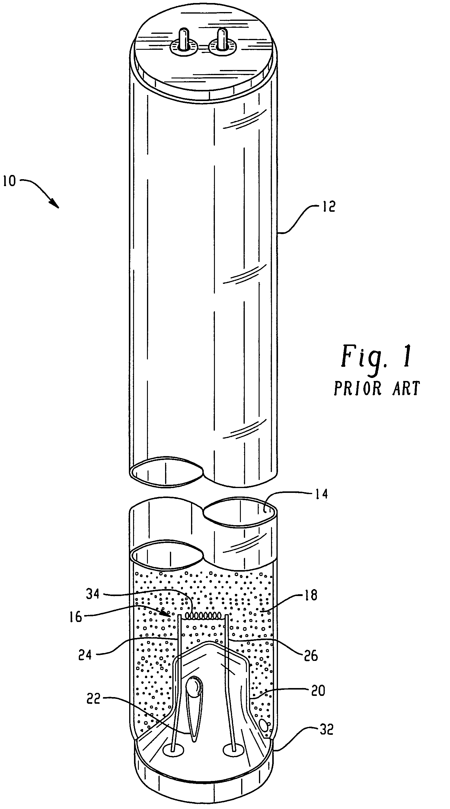
Although fluorescent lamps have numerous advantages relative to incandescent sources, these lamps still suffer from a number of disadvantages.
For example, the ionizable material and fill gases used to generate the illumination pattern are relatively hazardous materials.
Moreover, fluorescent lamps require the use of a ballast transformer to cause the fluorescent lamps to illuminate.
Ballasts frequently fail and require replacement.
Moreover, as noted above, the energy costs for operating fluorescent lamps need further improvement.

Method used


Image

  • Retrofit light emitting diode tube
  • Retrofit light emitting diode tube
  • Retrofit light emitting diode tube

Examples


Embodiment Construction

[0022]The present disclosure is directed to a solid-state lamp employing light emissive diodes (LEDs) that are designed as a replacement illumination source for fluorescent lamps. The solid-state lamp, hereinafter referred to as a retrofit LED light tube, may be configured as a replacement for a variety of fluorescent lighting applications. In a preferred embodiment, the LED light tube is adapted for use in so-called troffer-type fluorescent lighting fixtures.

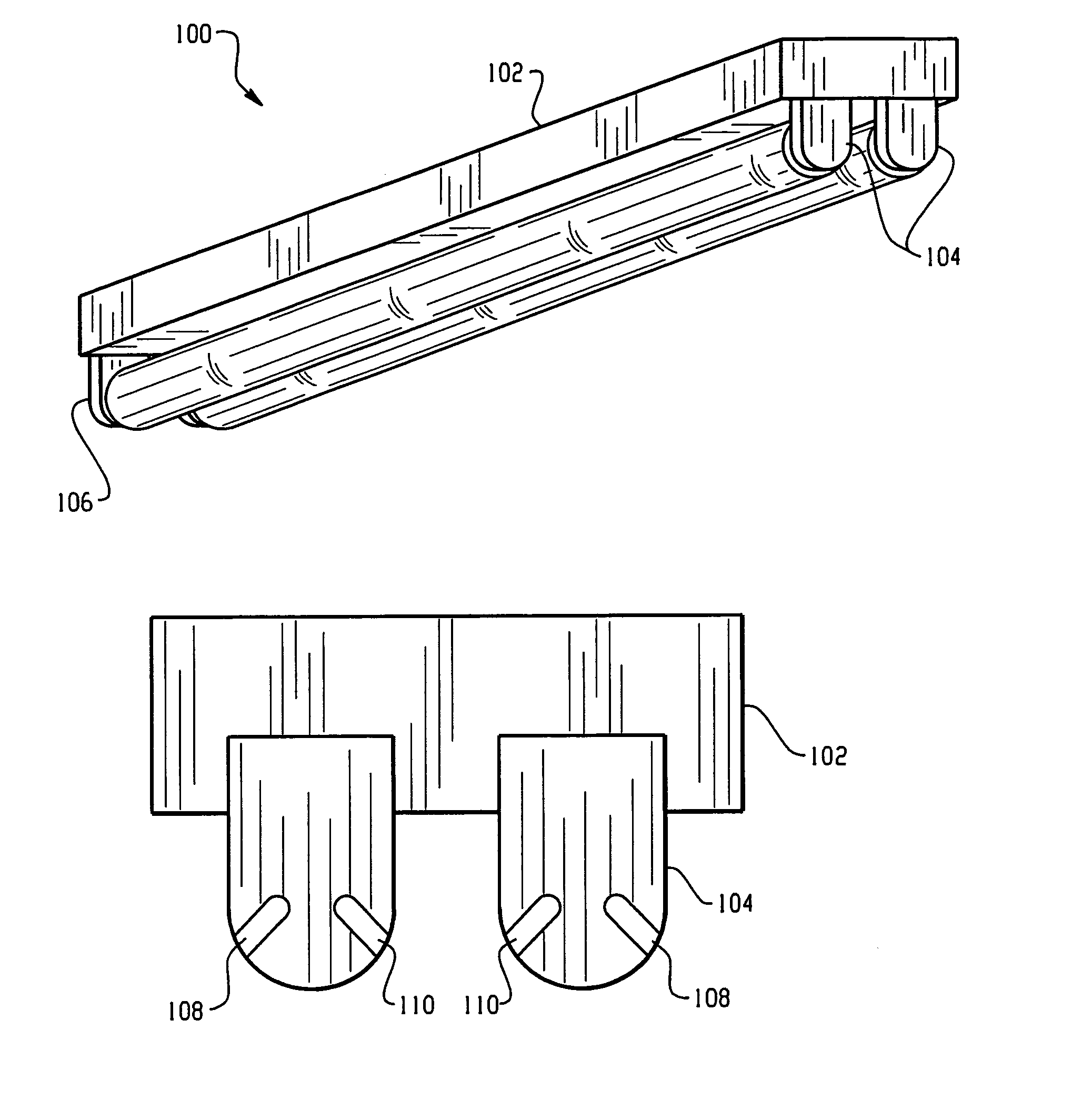
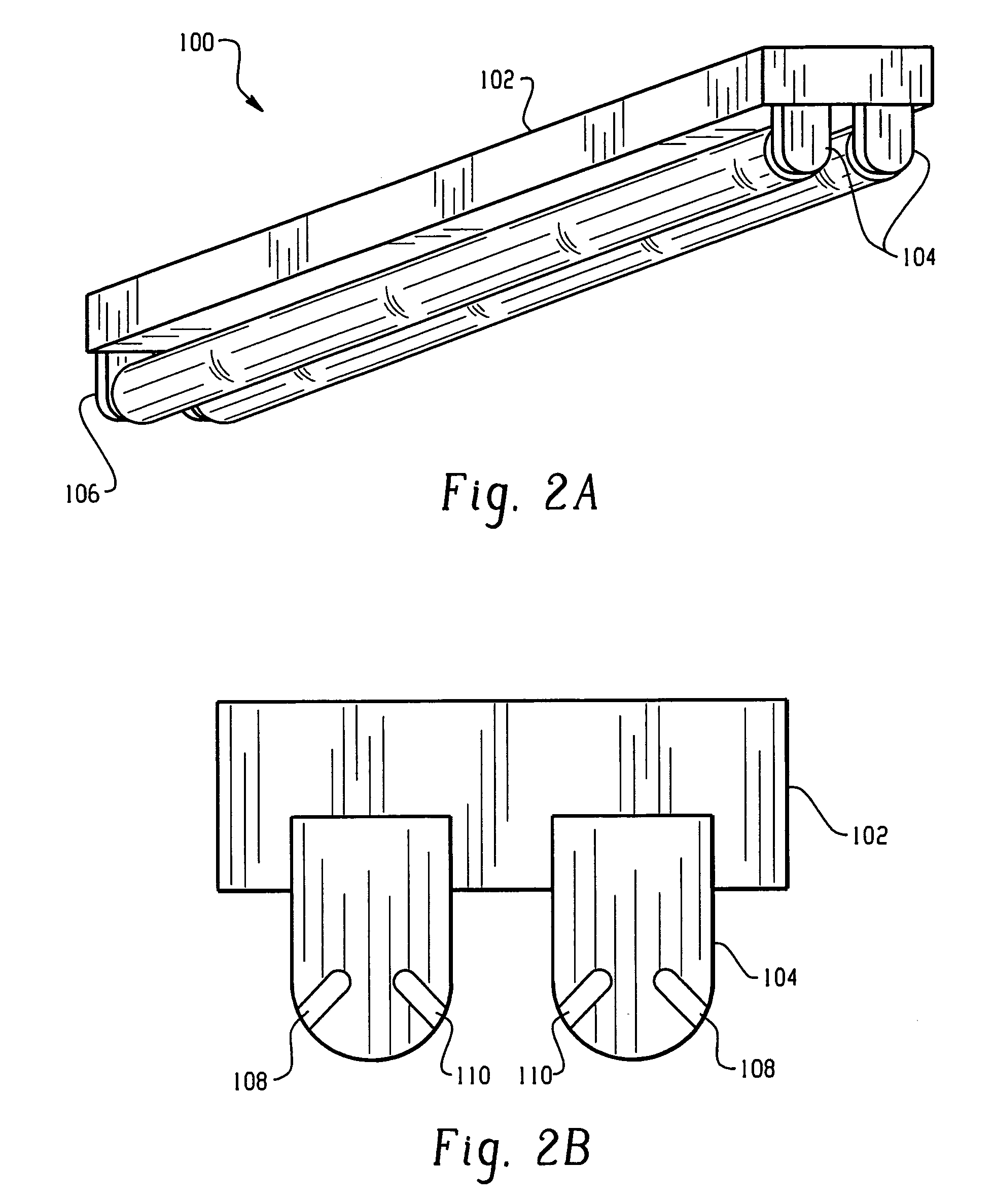
[0023]Referring now to FIGS. 2A and 2B, there is shown a troffer fixture assembly 100 suitable for use with the retrofit LED light tube. The troffer assembly is exemplary only, other troffer assemblies suitable for use will be apparent to those skilled in the art in view of this disclosure. The troffer fixture assembly 100 includes a square or rectangular housing 102 typically used with one or more fluorescent light bulbs. The housing 102 comprises a substantially planar body and optional sidewalls depending from the body porti...


PUM

PropertyMeasurementUnit
DC voltageaaaaaaaaaa
frequencyaaaaaaaaaa
voltageaaaaaaaaaa

Abstract

An LED light tube for replacement for fluorescent light tubes includes an elongated cylindrical transparent envelope, a base cap at each end of the envelope, and at least one LED device in electrical communication with the base cap. The LED light tube is adapted for use in troffer light fixtures.

Description

CROSS REFERENCE TO RELATED APPLICATION[0001]This application is a divisional of U.S. patent application Ser. No. 09 / 998,274, which is now U.S. Pat. No. 6,936,968, filed on Nov. 30, 2001.BACKGROUND OF THE INVENTION[0002]The present disclosure relates to light bulbs and in particular, to light bulbs comprised of light emitting diodes.[0003]There are millions of light fixtures installed and being produced each year to provide both task and general lighting within schools, offices, homes, marine vessels, aircraft and the like. In recent decades, more and more of these applications have been addressed with the use of a fluorescent lamp as the light source. The advent of fluorescent lighting has been shown to be a significant improvement over incandescent light fixtures. Noted advantages are numerous and include a marked reduction in energy consumption for a given light output, reduced operating temperatures and a “cooler” light rendition index.[0004]Fluorescent lamps are generally charac...

Claims


Application Information

Patent Timeline
Patent Type & Authority Patents(United States)
IPC IPC(8): H01J13/46F21K99/00H05B44/00
CPCF21K9/17H05B33/0803H05B33/0809F21Y2101/02F21Y2103/003Y02B20/386F21Y2111/008F21K9/27F21Y2103/10F21Y2115/10F21Y2107/60F21Y2107/90Y02B20/30H05B45/305H05B45/382H05B45/3578
Inventor CROSS, ROBERT PORTERCROSS, ROBERT HARTWELLCROSS, JEFFREY PARKER
Owner MULE LIGHTING
Learn More