Equivalent circuits and simulation method for an RF switch

a technology of equal circuits and simulation methods, applied in the field of equal circuits, can solve the problems of reducing the size of rf elements and the inability of prior art circuit simulation software to simulate an rf switch correctly

Active Publication Date: 2006-06-13
UNITED MICROELECTRONICS CORP
View PDF0 Cites 5 Cited by
  • Summary
  • Abstract
  • Description
  • Claims
  • Application Information

AI Technical Summary

Problems solved by technology

However, as the operating frequency of wireless devices increases and the size of RF elements reduces, the prior art circuit simulation software cannot be used to simulate an RF switch correctly.

Method used


Image

  • Equivalent circuits and simulation method for an RF switch
  • Equivalent circuits and simulation method for an RF switch
  • Equivalent circuits and simulation method for an RF switch

Examples


Embodiment Construction

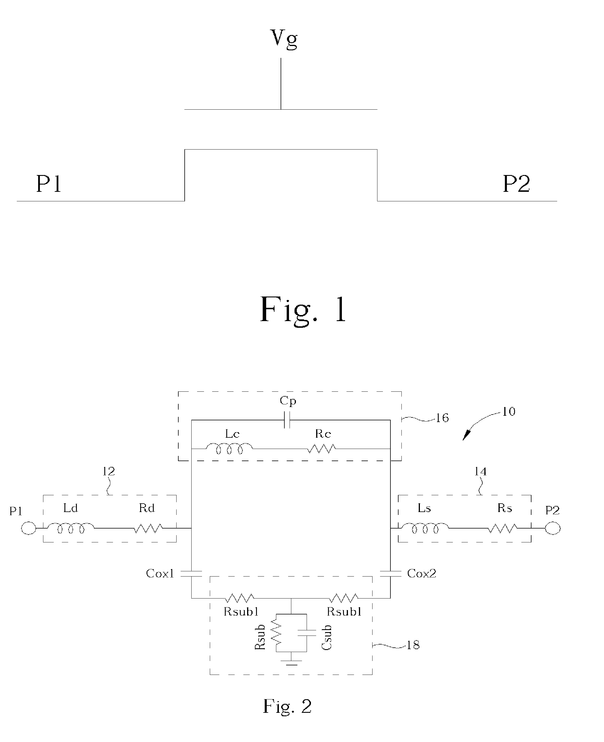
[0012]Please refer to FIG. 1, which is a schematic diagram of an RF switch. The RF switch is an N-type metal-oxide semiconductor (NMOS) transistor, having a drain taken as an input port P1 for inputting an RF signal, a gate for turning the NMOS transistor on / off, and a source taken as an output port P2 for outputting the RF signal. When the NMOS transistor is turned on, the output port P2 outputs the RF signal received from the input port P1. When the NMOS transistor is turned off, the RF signal is obstructed from being outputted from the output port P2.

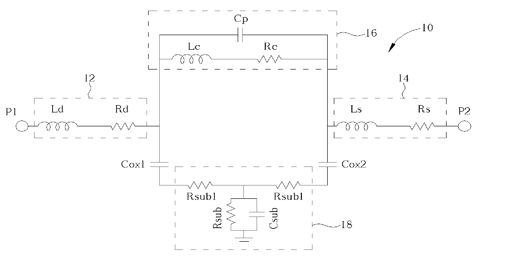
[0013]Please refer to FIG. 2, which is a circuit diagram of a first equivalent circuit 10 of the RF switch shown in FIG. 1. The first equivalent circuit 10 is used to simulate the RF switch at a turned-off state. The first equivalent circuit 10 comprises a first block 12, a second block 14, a third block 16, a first gate-substrate capacitor Cox1, a second gate-substrate capacitor Cox2, and a fourth block 19. The first block 12 is con...


PUM


Abstract

Equivalent circuits and a simulation method for simulating an RF switch are disclosed. The equivalent circuits are a first equivalent circuit and a second equivalent circuit, and are formed by resistors, capacitors, and inductors. The method includes using the first equivalent circuit to simulate the switch at a turned-off state and using the second equivalent circuit to simulate the switch at a turned-on state.

Description

BACKGROUND OF INVENTION[0001]1. Field of the Invention[0002]The present invention relates to an equivalent circuit and a method thereof for simulating a switch, and more particularly, to equivalent circuit and a method thereof for simulating an RF switch.[0003]2. Description of the Prior Art[0004]Due to the rapid development of wireless communication systems, wireless devices offering great convenience are widely used in daily communications. With wireless devices, people are able to exchange information, share experiences, and communicate with each other anytime and anywhere. Because of the wide usage of wireless devices, more various and new wireless products are developed. To shorten the flow path of a new wireless product, before the production of the new wireless product, the manufacturer usually uses circuit simulation software to analyze the electrical characteristics of the new wireless product, and then estimates and improves the quality of the circuit of the new wireless p...

Claims


Application Information

Patent Timeline
Patent Type & Authority Patents(United States)
IPC IPC(8): H01P1/10G06F17/50
CPCG06F17/5036G06F30/367
Inventor LEE, YUE-SHIUNCHEN, CHENG-HSIUNG
Owner UNITED MICROELECTRONICS CORP
Why Eureka
Try Eureka