Arch bridge

Inactive Publication Date: 2006-06-20
MORRIS DAVID C
View PDF4 Cites 29 Cited by
  • Summary
  • Abstract
  • Description
  • Claims
  • Application Information

AI Technical Summary

Problems solved by technology

Although a great many bridge designs have already been introduced, it is neverth

Method used


Image

  • Arch bridge
  • Arch bridge
  • Arch bridge

Examples


Embodiment Construction

)

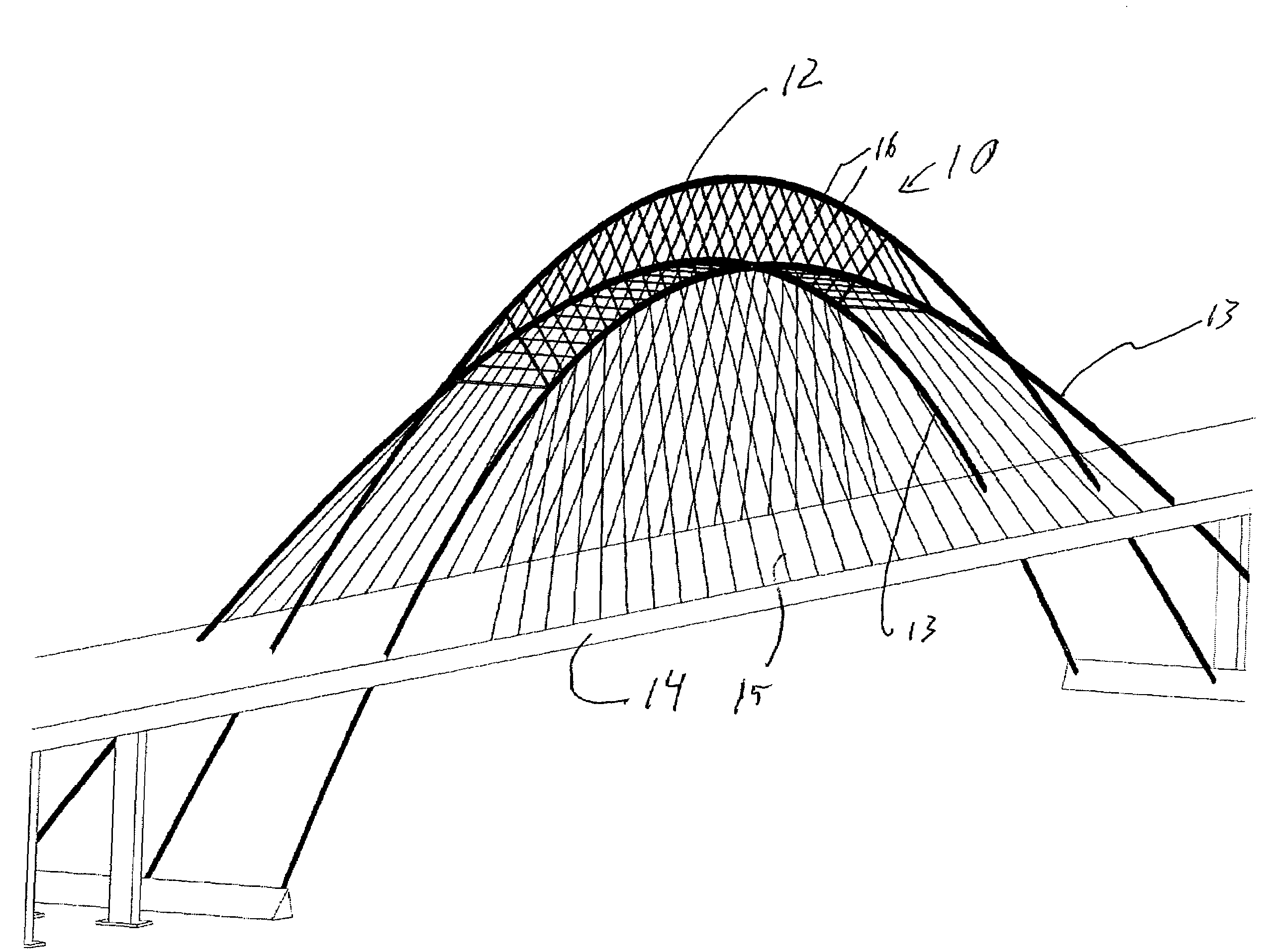
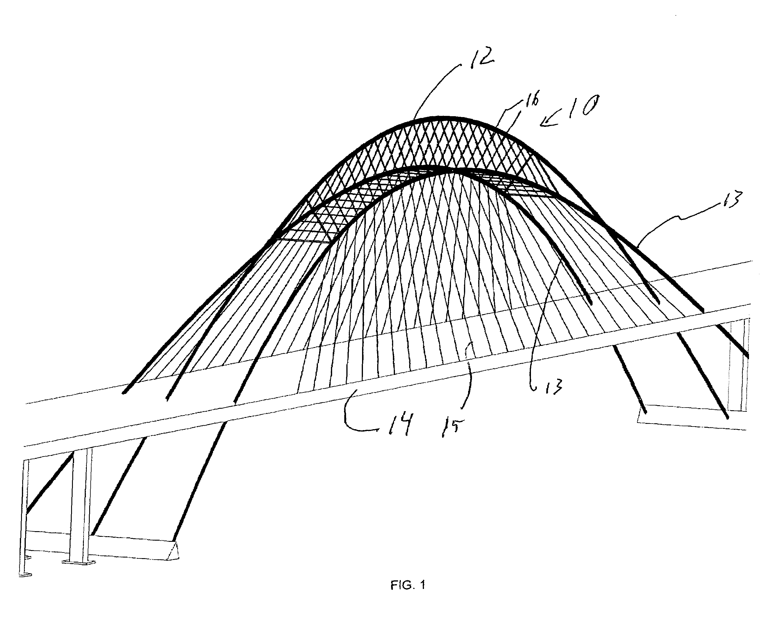
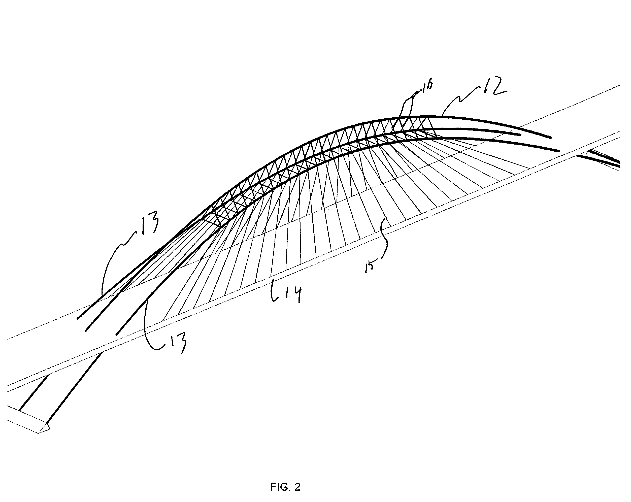
[0014]One preferred embodiment is in the form of a bridge 10 has a center longitudinal arch 12 and two side arches 13 from which a deck 14 is suspended by a set of cables 15. All three arches 12 and 13 extend from below the suspended deck 14 and arch high over the middle of the bridge's 10 longitudinal expanse. The center, uppermost, arch 12 rises from and descends back through the center of the bridge's width. The two external arches 13 rise from and descend on either side of the width of bridge 10. Above the deck 14 external arches 13 are connected each other and to the center arch 12 and by a longitudinal array of transverse beam sets 16, each in the form of a triangle. One of the sets 16 is placed at the apex of the three arches 12, with the remaining sets 16 spaced equal distances apart, on each side of the apex and descending on either longitudinal side. Referring to FIG. 3, in an alternative preferred embodiment 10′ a center arch 12′ is lower than the two side arches 13′.

[00...


PUM


Abstract

A bridge, comprising a set of arches, each extending longitudinally along the bridge, including at least one central arch and at least two side arches, symmetrically disposed about the central arch. The side arches are slanted transversely inwardly so that they are closest at the longitudinal center of the bridge and are generally disposed either above or below the central arch. In addition, transverse members connect the arches together and a deck is suspended from the set of arches.

Description

RELATED APPLICATIONS[0001]This application claims priority from provisional application 60 / 633,835 and 60 / 633,836, both filed on Dec. 6, 2005; and provisional application 60 / 635,089 filed Dec. 10, 2004.BACKGROUND OF THE INVENTION[0002]A successful bridge design should be gracious, resilient to earthquakes and the elements in general, and inexpensive to construct. Although a great many bridge designs have already been introduced, it is nevertheless true that not all problems associated with bridge design have been solved. Accordingly, additional, novel bridge designs may yield benefits currently not available in the library of designs.SUMMARY[0003]The following embodiments and aspects thereof are described and illustrated in conjunction with systems, tools and methods which are meant to be exemplary and illustrative, not limiting in scope. In various embodiments, one or more of the above-described problems have been reduced or eliminated, while other embodiments are directed to other...

Claims


Application Information

Patent Timeline
IPC IPC(8): E01D4/00E01D11/00
CPCE01D4/00E01D1/005
Inventor MORRIS, DAVID C.
Owner MORRIS DAVID C
Why Eureka
Try Eureka