
Foot bath

a foot bath and foot technology, applied in baths, physical therapy, construction, etc., can solve the problems of asymmetric and uneven fluid flow patterns produced by limited prior art foot baths in the therapeutic results they produce, and limited foot baths in the therapeutic results

Inactive Publication Date: 2006-06-27
CONAIR CIP INC
View PDF70 Cites 15 Cited by
  • Summary
  • Abstract
  • Description
  • Claims
  • Application Information

AI Technical Summary

Benefits of technology

"The present invention provides a foot bath with an adjustable water jet that controls the flow pattern of the water in the foot bath. This allows for a vortex, elliptical, or circular flow pattern, which helps to circulate the water in the foot bath. The foot bath also has a housing with an inner wall that defines a reservoir, a water jet for circulating the fluid in the reservoir, and a pump for pumping the fluid to the jet. This results in a predetermined flow pattern for the fluid in the reservoir. Overall, this invention provides a more effective and efficient way to enjoy a foot bath experience."

Problems solved by technology

However, the prior art foot therapy devices are limited.
Prior art foot therapy devices are limited in the therapeutic results they produce since they fail to produce an effective massaging sensation and therapy attributed from the continuous movement or circulation of the fluid disposed in the foot therapy device.
This chaotic and random flow pattern is distracting and aesthetically displeasing to the user, especially in the instance of massage therapy.
Thus, uneven and random fluid flow patterns produced by the prior art may be asymmetric based on the shape of the bowl.
The flow patterns, if any, are generally uninviting and undesirable as they are distracting to the user.
Further, prior art foot therapy devices do not provide a relaxing liquid flow pattern or an attendant massage therapy from the liquid flow pattern.

Method used


Image

  • Foot bath
  • Foot bath
  • Foot bath

Examples


Embodiment Construction

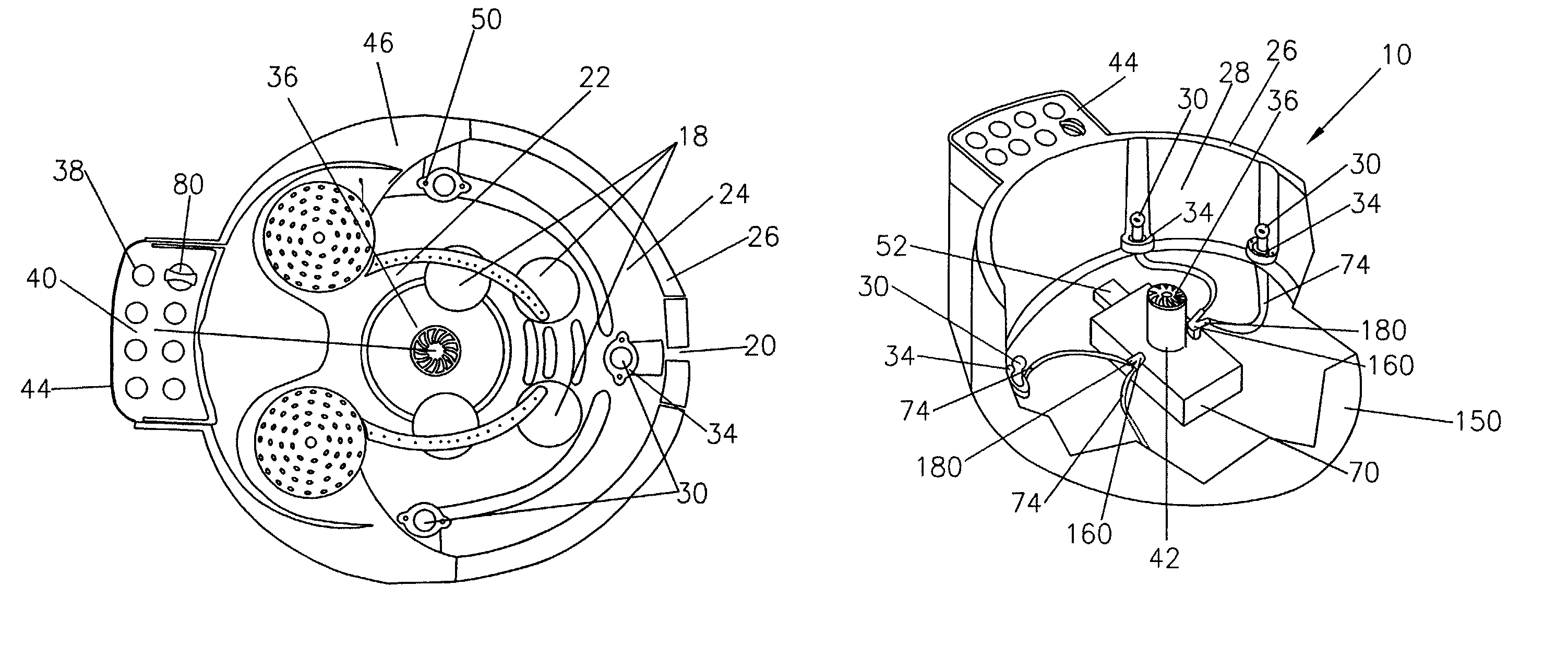
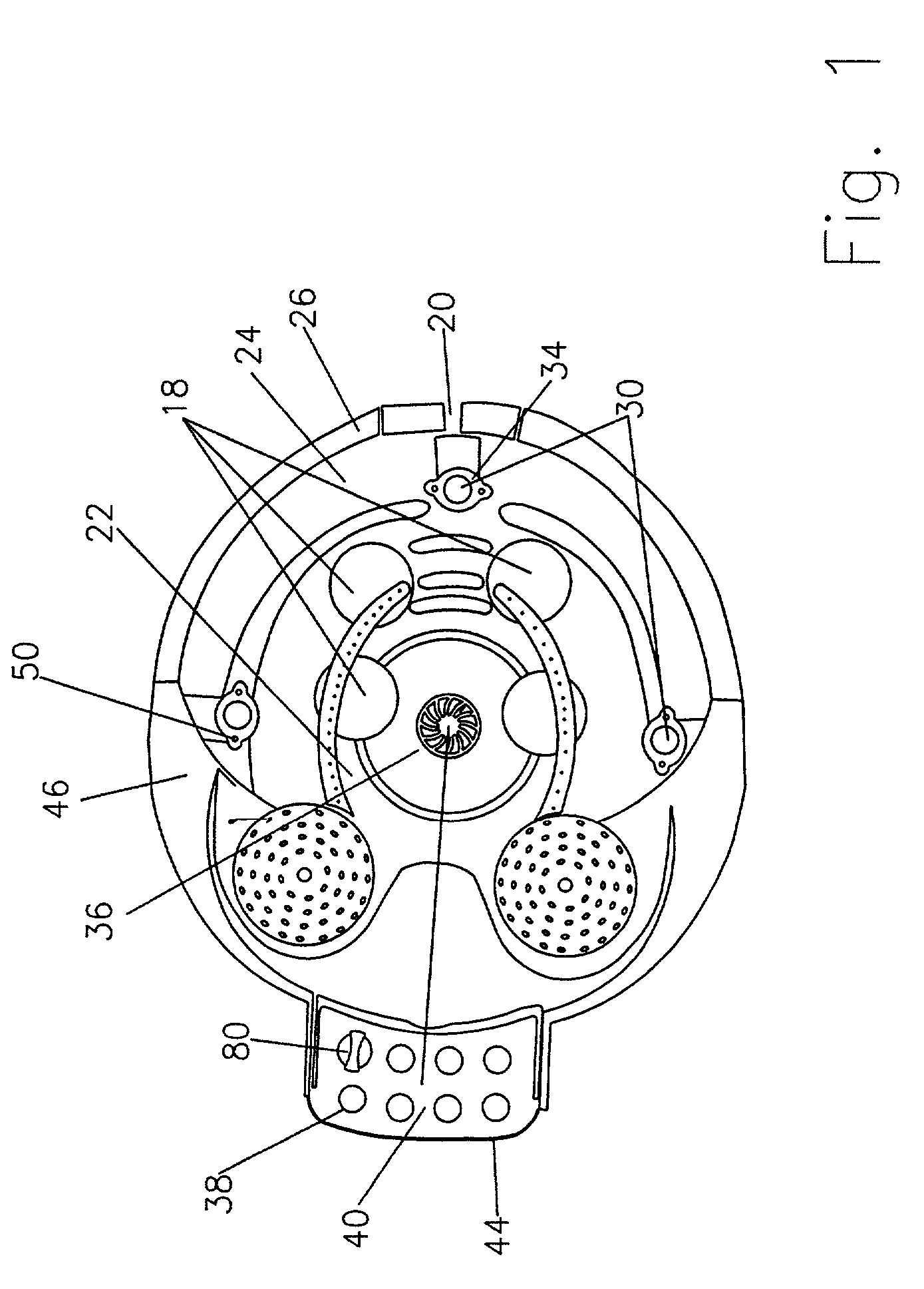
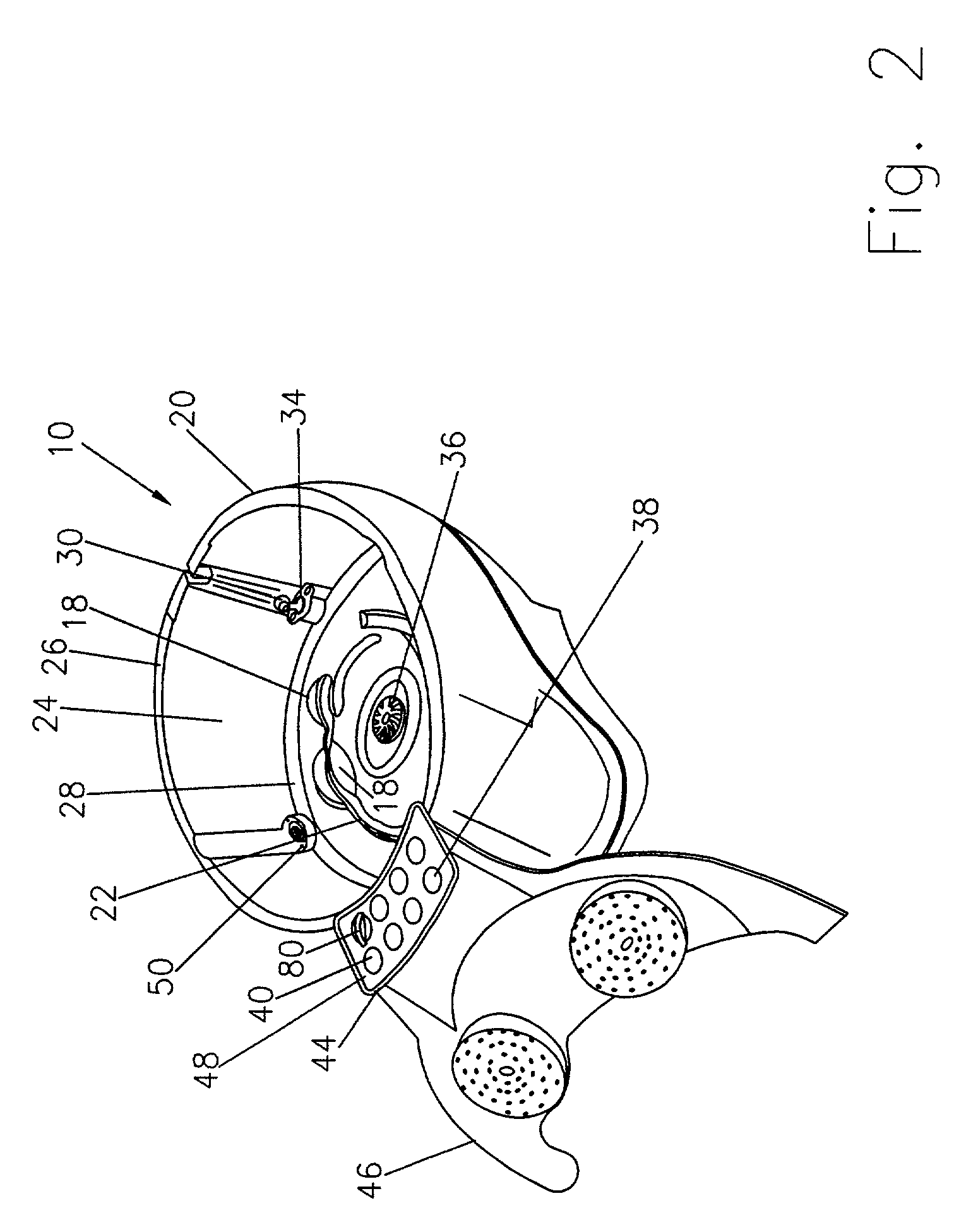
[0016]Referring to the drawings and in particular FIG. 1, there is provided a foot bath generally represented by reference numeral 10. Foot bath 10 includes a housing 20. Housing 20 has a floor 22, a sidewall 24 and a top wall or lip 26. Floor 22 and sidewalls 24 define a reservoir 28 for containing liquid. Feet and other body tissues of the user may be placed into reservoir 28 for therapeutic and relaxing massaging.

[0017]In an aspect of the present invention, floor 22 preferably has a number of adjustable water jets 30 disposed on or near floor 22. Water jets 30 extend through corresponding apertures 34 in floor 22. Apertures 34 are sealed or otherwise allow water jets 30 to extend through floor 22, in a water tight configuration.

[0018]Floor 22 has a number of raised contours 18 positioned thereon for facilitating the comfortable placement of the feet thereon. Floor 22 also includes a drain 36. Drain 36 is preferably disposed in the centermost region of floor 22. An exemplary aspec...


PUM


Abstract

A foot therapy device is provided. The foot therapy device includes a housing having a side wall, and a floor defining a reservoir for receiving a fluid. The foot therapy device has at least one water jet disposed in the reservoir and a pump for pumping the fluid in the reservoir to the water jet. The water jet circulates the fluid disposed in the reservoir. The fluid circulates in a predetermined fluid flow pattern in the reservoir. The predetermined flow pattern of the fluid may include a substantially circular, elliptical or vortex motion for a relaxing and pleasant massage therapy.

Description

BACKGROUND OF THE INVENTION[0001]1. Field of the Invention[0002]The present invention relates to a foot bath therapy device. More particularly, the present invention relates to a portable foot bath having a reservoir with a plurality of adjustable jets disposed on a floor of the reservoir for creating a circular water flow pattern for massage therapy.[0003]2. Description of the Prior Art[0004]In the prior art, there are various known foot therapy massagers and bath devices. A number of these devices are capable of massaging the feet with dry heat, a vibrating massage with a liquid bath, or a supplemental heater. The prior art foot therapy devices may also provide a variety of vibrating massage sensations with a cold or hot liquid, and aerated bubble massage sensations, either alone or in combination. Generally, an objective in the prior art foot therapy devices is to provide relief to a user by increasing blood circulation in the feet by providing soothing, therapeutic stimulus to t...

Claims


Application Information

Patent Timeline
Patent Type & Authority Patents(United States)
IPC IPC(8): A47K3/022A61H33/00E03C1/00A61H35/00
CPCA47K3/022A61H33/0087A61H33/6021A61H35/006A61H33/6068
Inventor LEUNG, ANTHONY KIT LUNFUNG, KAM FAI
Owner CONAIR CIP INC
Learn More