

Method and apparatus for distance measurement
a distance measurement and distance technology, applied in the direction of distance measurement, active open surveying means, instruments, etc., can solve the problems of inability to use a remote location to measure the distance between two arbitrary points, tedious and time-consuming process,
- Summary
- Abstract
- Description
- Claims
- Application Information
AI Technical Summary
Benefits of technology
Problems solved by technology
Method used
Image

Examples
Embodiment Construction
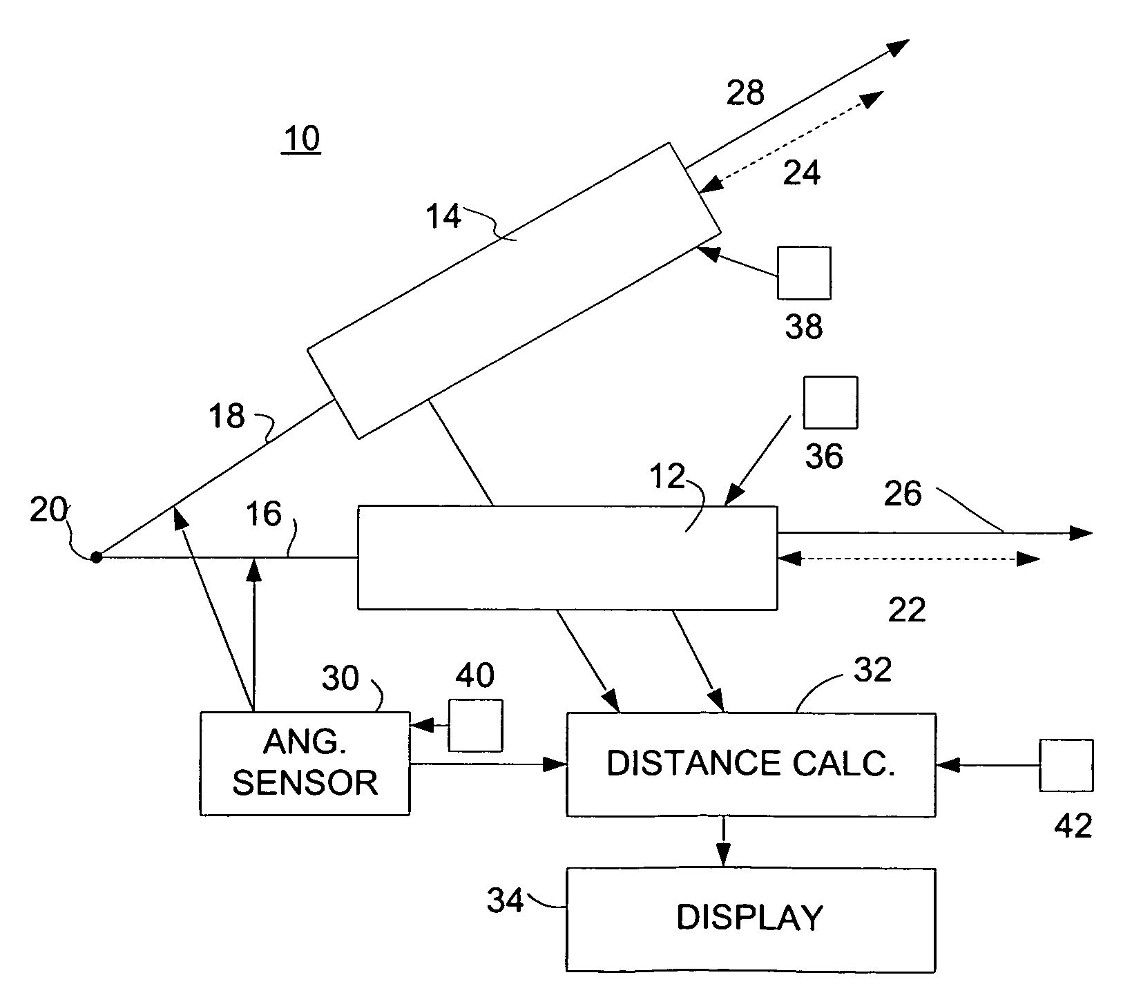
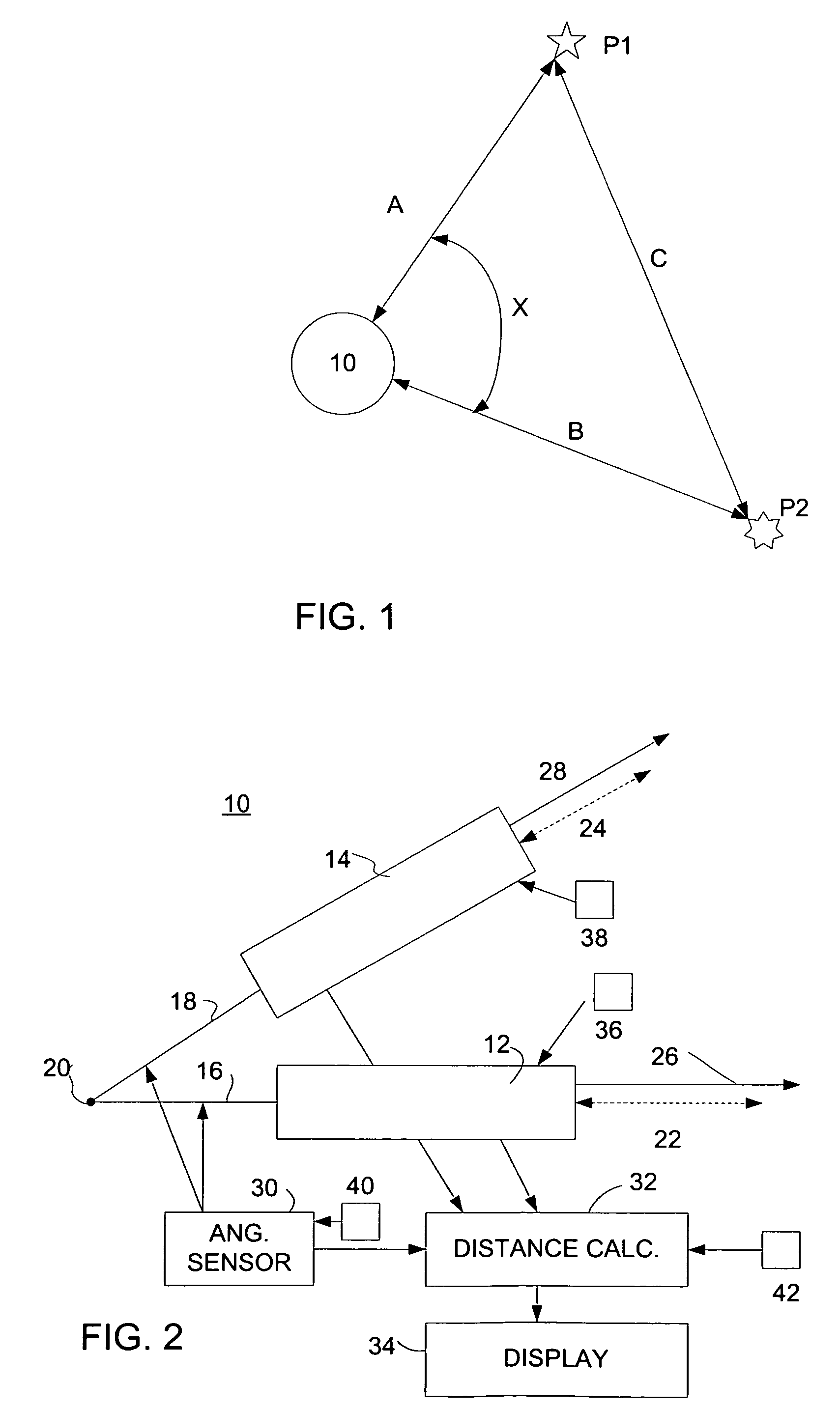
[0021]Referring now to FIG. 1, a device 10 constructed in accordance with this invention is used to determine the distance C between two points P1 and P2. As shown in FIG. 1, the two points can be two different objects, or they can be points disposed on the same object. The distance is determined by generating a first beam and targeting it at point P1, generating a second beam at a known angle X with respect to the first beam and targeting it at point P2. The device 10 uses these beams to measure the distance A to point P1 and distance B to point P2. These distances can be determined by using any of the technique well known in the art. Moreover, as discussed in more detail below, the two beams can be generated by the same, or by two different components, and can be generated simultaneously, or sequentially. The device 10 also measures the angle X between the two beams.
[0022]Once these parameters are known, the distance C can be calculated using well known principles. For example, th...
PUM
 Abstract
Description
Claims
Application Information