Modulated control circuit and method for current-limited dimming and color mixing of display and illumination systems

a control circuit and module technology, applied in the direction of process and machine control, instruments, light sources, etc., can solve the problems of asymmetric power supply load, short useful life, and faster deformation of forward current levels, and achieve the effect of reducing the number of modules

Active Publication Date: 2006-08-08
BOCA FLASHER
View PDF10 Cites 204 Cited by
  • Summary
  • Abstract
  • Description
  • Claims
  • Application Information

AI Technical Summary

Benefits of technology

[0019]The present invention is directed to a lighting controller for LED products, particularly those that employ dimming and color changing effects. An advantage of the present invention is that it enhances control of an analog current limiting circuit when it is operated at low current levels. The present invention provides greater control over illumination intensity and hue for LED lighting systems by reducing differences in illumination intensity among LEDs in separate control strings and also minimizing color shifts at low levels of output illumination. The present invention also reduces the difficulties relating to EMI and asymmetric power supply loading effects found in PWM and FM control methods. Further advantages of the invention will become apparent to those of ordinary skill in the art through the disclosure herein. The advantages of the present invention can be obtained by using a modulated analog control LED dimming circuit with only a minimal addition of components or control signals.
[0020]One aspect of the invention relates to a method for controlling the intensity of an illumination source, such as an LED, by providing an input signal to a circuit containing the illumination source, and varying the input signal over a first range of illumination intensities so that the intensity of the illumination source varies in proportion to the voltage of the input signal; and varying the input signal over a second range of illumination intensities of said illumination source such that the intensity of said illumination source varies in proportion to the voltage of the input signal and the input signal is pulsed between any two or more discrete voltage levels.
[0021]Another aspect of the invention relates to an illumination control circuit comprising: a controlling module having one or more analog output signals producing output control voltages each individually variable within a range of values; one or more intensity modules receiving said analog output signals of said controlling module to control one or more illumination sources; wherein said intensity modules are controlled according to said analog output signals of said controlling module to vary the intensity of said illumination sources in proportion to the voltage level of said analog output signals, and additionally in response to a pulsing of said analog output signals between any two or more discrete voltage levels.
[0022]The advantages of the present invention can be obtained using a microcontroller having an input / output port and one or more output signals; said output signals of said microcontroller each having a first state and a second state; one or more digital-to-analog converters each having as an input the input / output port from said microcontroller, and each having an output signal; one or more switching devices each having as a first input the output signal from one of said digital-to-analog converters and each having as a second input one of said output signals from said microcontroller, and each having an analog output signal; wherein each of said analog output signals from each of said switching devices is controlled according to the output signal from one of said digital-to-analog converters when the corresponding output signal of said microcontroller is in its first state, and each of said analog output signals is connected to ground when the corresponding output signal of said microcontroller is in its second state.
[0023]Another aspect of the invention relates to an illumination control circuit comprising, for example: a microcontroller adapted to write an output control signal to a digital-to-analog converter according to programmed instructions; said digital-to-analog converter having an analog output signal that varies according to said output control signal of said microcontroller; a switching device receiving said analog output signal of said digital-to-analog converter to control an illumination source; wherein said switching device is controlled according to said analog output signal of said digital-to-analog converter to vary the intensity of said illumination source over a first range of illumination intensities of said illumination source such that the intensity of the illumination source varies in proportion to the voltage of said analog output signal of said digital-to-analog converter, and a second range of illumination intensities of said illumination source such that the intensity of said illumination source varies in proportion to the voltage of said analog output signal of said digital-to-analog converter and said analog output signal of said digital-to-analog converter is pulsed between any two or more discrete voltage levels.

Problems solved by technology

LEDs driven at higher levels of forward current will degrade faster, and therefore have a shorter useful life, than the same LEDs driven at lower levels of forward current.
Although PWM schemes are common, there are several disadvantages to this method of LED intensity control.
This can create two problems.
First, the rapid on and off switching of the system can create asymmetric power supply loading.
Second, the pulsing of the current through electrical leads can create difficult to manage electromagnetic interference (EMI) problems because such leads may act as transmitters of radiofrequency energy that may interfere with other devices operating at similar frequencies.
The FM method, however, suffers from the same drawbacks of the PWM method when the dimming level is held constant, or is changing at a relatively slow rate.
As the size of the lighting system (total number of LEDs) controlled by a central control and power supply gets large, these negative effects can get correspondingly large and difficult to overcome.
The Analog Control method, although solving the problems associated with PWM and FM techniques for LED driving, nevertheless has other drawbacks.
In addition, wavelength shifts can occur especially at lower current levels, which can lead to undesired color shifts in the light output by the LEDs.

Method used


Image

  • Modulated control circuit and method for current-limited dimming and color mixing of display and illumination systems
  • Modulated control circuit and method for current-limited dimming and color mixing of display and illumination systems
  • Modulated control circuit and method for current-limited dimming and color mixing of display and illumination systems

Examples


Embodiment Construction

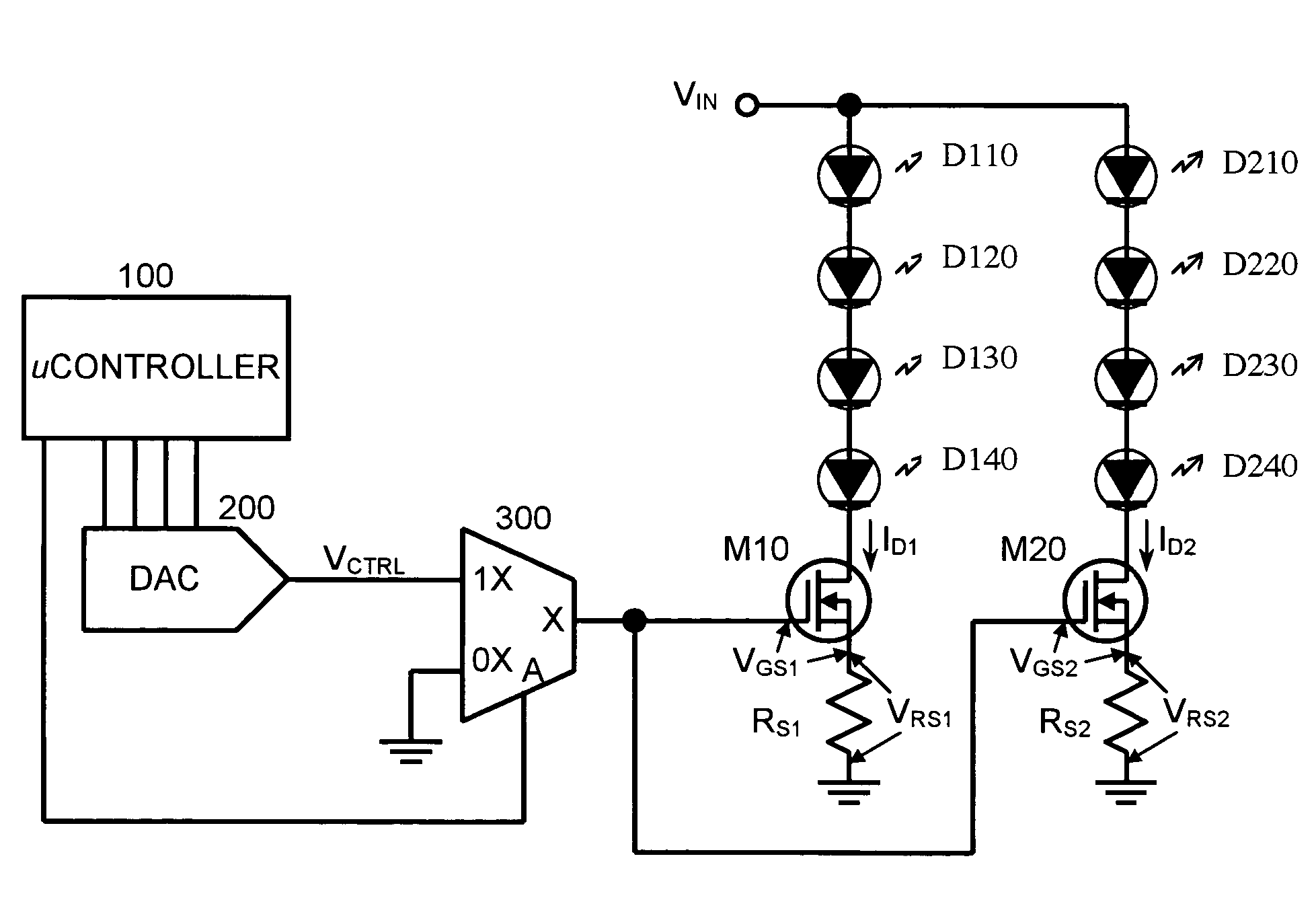
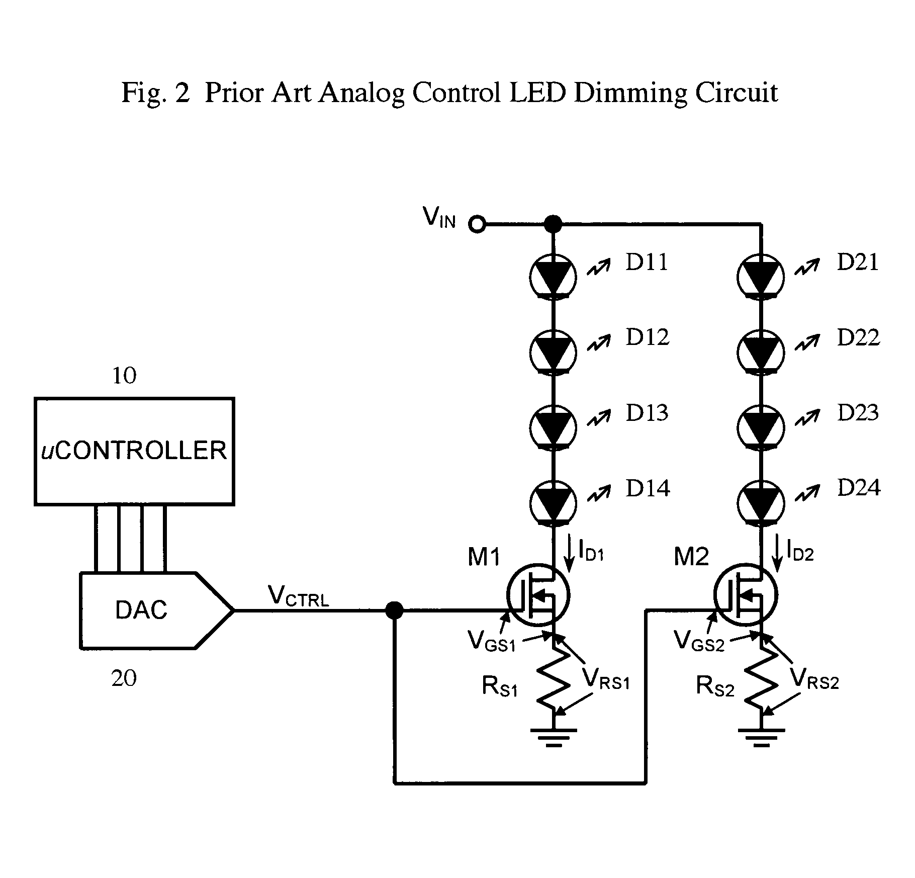
[0024]The present invention is best understood in relation to the prior art Analog Control circuit. FIG. 2 shows a prior art analog control LED dimming circuit. Switching devices, such as metal oxide semiconductor field effect transistors (MOSFETs) M1 and M2 along with source resistors RS1 and RS2 provide the current limiting function for their respective series strings of LEDs D11, D12, D13, D14 and D21, D22, D23, D24, respectively. That is, MOSFETs M1 and M2 and resistors RS1 and RS2, respectively, vary the current output to the LEDs in accordance with the voltage level of the signal input into the MOSFETs. Input / output port of microcontroller 10 is coupled to a digital analog converter 20 which provides the analog control voltage VCTRL to MOSFETs M1 and M2. Concentrating on the first current limiting circuit, it can be seen that with the DAC output at Ground potential (VCTRL=0V), the Gate-to-Source voltage (VGS1) of MOSFET M1 will be 0V, and the MOSFET will be off. Thus, no curre...


PUM


Abstract

A control circuit for a lighting system allows analog control over a first range of illumination intensities in which the intensity of the illumination source varies in proportion to the voltage level of the control signal. The circuit provides for improved dimming and color mixing capability by allowing pulse width or frequency modulation control in addition to analog control over a second range of illumination intensities.

Description

FIELD OF THE INVENTION[0001]This invention relates to controllers for illumination devices such as LEDs (light emitting diodes). The use of LEDs in illumination systems is well known. These devices are especially useful for lighting components, systems, and finished goods. LED lighting is a fast growing segment of the lighting industry due to the efficiency, reliability and longevity of LEDs. Product usage applications include but are not limited to interior and exterior signage, cove lighting, architectural lighting, display case lighting, under water lighting, marine lighting, and many others. The present invention includes lighting controllers compatible with LED bulbs, color changing LED strips, color wash controllers, LED brick lights, LED color changing disks, LED traffic / warning lights, sign modules and the like. Although the preferred embodiments of the invention are discussed in relation to LED devices, it should be understood that the present invention can be applied to ot...

Claims


Application Information

Patent Timeline
Patent Type & Authority Patents(United States)
IPC IPC(8): G05F1/00H05B39/00
CPCH05B33/086H05B33/0818H05B45/20
Inventor MCKINNEY, STEVEN J.POLAK, MATTHEW C.
Owner BOCA FLASHER
Why Eureka
Try Eureka