Method for operating a power plant by means of a CO2 process

a technology of co2 and power plant, which is applied in the direction of hot gas positive displacement engine plants, indirect carbon-dioxide mitigation, combustion engines, etc., can solve the problems of inability to implement such a procedure, the co2 separation problem is only marginally reduced, and the co2 separation problem remains. , to achieve the effect of simple retreatment and less cos

Inactive Publication Date: 2006-08-15
ALSTOM SA
View PDF14 Cites 151 Cited by
  • Summary
  • Abstract
  • Description
  • Claims
  • Application Information

AI Technical Summary

Benefits of technology

[0015]Another essential advantage of the invention is to be seen in that the method can be carried out by means of several types of gas turbine setups, the setup described in each case constituting a specific optimum solution as a function of the predetermined parameters.
[0016]Another essential advantage of the invention is to be seen in that it provides a remedy against the fact that all air-breathing internal combustion engines also generate nitric oxides which act as air pollutants and the production of which requires costly measures to combat it, not least in light of the internationally restrictive laws on permissible pollutant emissions. Since no atmospheric nitrogen enters the flame in the recirculation mode with pure oxygen, NOx is also not generated. Admittedly, if the fuel carries bound nitrogen with it, a slight formation of NOx must be expected. However, since the excess gas represents a much smaller quantity than the exhaust gas in the air mode, its retreatment is simpler and less expensive.
[0017]Advantageous and expedient developments of the solutions according to the invention for achieving the object are defined in the further claims.
[0018]Exemplary embodiments of the invention are explained in more detail below with reference to the drawings. All the features not essential for an immediate understanding of the invention have been omitted. Identical elements are given the same reference symbols in the various figures. The direction of flow of the media is indicated by arrows.

Problems solved by technology

Extended use of fossil fuels nowadays releases CO2 quantities which are internationally recognized as a risk to the world climate.
However, the large volume flow makes it impossible to put such a procedure into practice.
In this case, however, the exhaust gas still remains mixed with the atmospheric nitrogen and the CO2 separation problem is therefore only marginally reduced.
Furthermore, all air-operated internal combustion engines also generate nitric oxides which act as air pollutants and the production of which requires costly measures to combat it.

Method used


Image

  • Method for operating a power plant by means of a CO2 process
  • Method for operating a power plant by means of a CO2 process
  • Method for operating a power plant by means of a CO2 process

Examples


Embodiment Construction

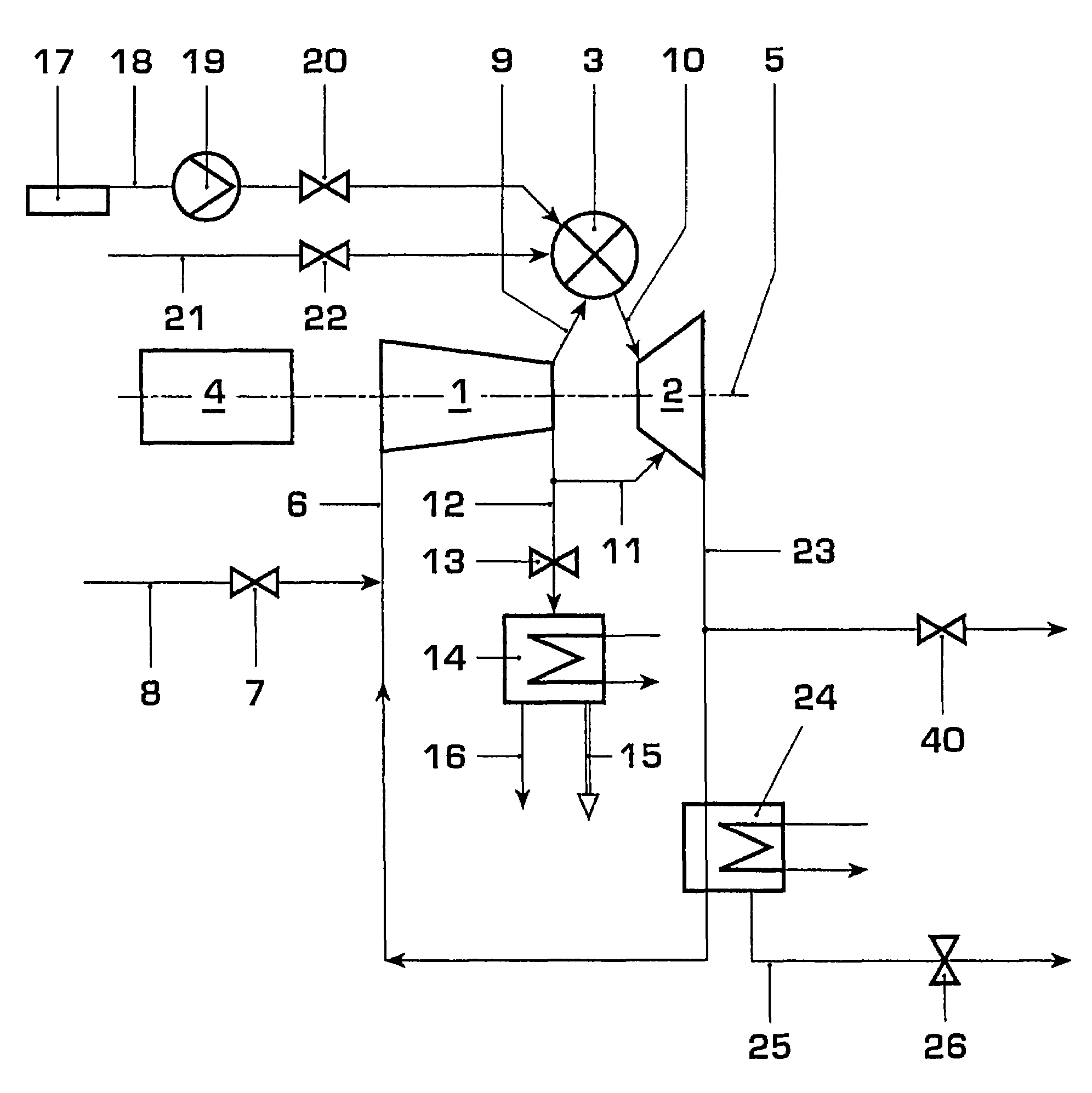
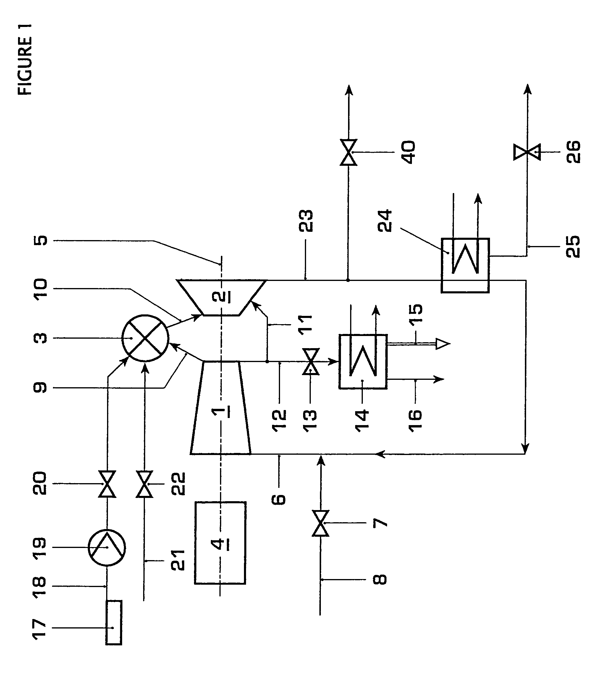
[0029]Referring now to the drawings, wherein like reference numerals designate identical or corresponding parts throughout the several views, FIG. 1 shows a gas turbine with a closed circuit. This gas turbine or gas turbo set consists, in terms of assemblies, of a compressor unit 1, of a generator 4 coupled to this compressor unit, of a turbine 2 coupled to the compressor unit and of a combustion chamber 3 acting between the compressor unit 1 and turbine 2. The turbomachines 1 and 2 can be coupled by means of a common shaft 5. The circuit medium 6, which is sucked in by the compressor unit 1 and which is predominantly CO2, flows, after compression has taken place, into the combustion chamber 3, in which the heat treatment of this medium is carried out, said medium then acting as hot gases 10 on the turbine 2. For startup, the compressor unit 1 may also, via a starting flap 7, suck in air 8, the nitrogen of which is discharged successively via an outlet flap 40 as said nitrogen is di...


PUM


Abstract

In a method for operating a power plant by means of a CO2 process, isentropic compression first takes place, subsequently an isobaric heat supply, then isentropic expansion, and finally isobaric heat discharge. The CO2 process broken down here takes place with internal combustion, a fuel (21) and the oxygen (18) necessary for oxidization being supplied. After the charging of the CO2 circuit (23) has been carried out, the excess CO2 formed from combustion is discharged continuously, in that this gas is led through a cooler (14), in which said gas is condensed. In order to dispose of this condensed CO2 (15), there are available here, for example, the possibilities of storing this CO2 on the ocean floor or of introducing the condensed CO2 into a worked-out deposit of natural gas.

Description

[0001]This application is a continuation of U.S. patent application Ser. No. 09 / 255,712 filed Feb. 23, 1999 now abandoned, which claims priority under 35 U.S.C. §§119 to EP 98 810 154.9 filed in Europe on Feb. 25, 1998; the entire content of which is hereby incorporated by reference.BACKGROUND OF THE INVENTION[0002]1. Field of the Invention[0003]The present invention relates to a method for operating a CO2 plant according to the preamble of claim 1. The invention also relates to setups for carrying out this method.[0004]2. Discussion of Background[0005]Internal combustion engines burn their fuel in compressed atmospheric air and mix their combustion gases intimately with this air and with the residual oxygen which has not been utilized. At the same time, the fuels, which almost always contain carbon, generate, inter alia, CO2 which is a greenhouse gas. Extended use of fossil fuels nowadays releases CO2 quantities which are internationally recognized as a risk to the world climate. A...

Claims


Application Information

Patent Timeline
Patent Type & Authority Patents(United States)
IPC IPC(8): F02C1/00F02C7/00F01K21/04F02C1/10
CPCF01K21/042F02C1/10F01K21/047Y02T10/16Y02E20/34Y02T10/12
Inventor FRUTSCHI, HANS ULRICHWETTSTEIN, HANS
Owner ALSTOM SA
Why Eureka
Try Eureka