
Vibration isolating mount

a technology of vibration isolation and mounting brackets, which is applied in the direction of machine supports, other domestic objects, mechanical apparatus, etc., can solve the problems of not optimally dampened or isolated, the coating mounting bracket is expensive to manufacture, and the noise is a bit loud

Inactive Publication Date: 2006-08-22
KINETICS NOISE CONTROL
View PDF28 Cites 28 Cited by
  • Summary
  • Abstract
  • Description
  • Claims
  • Application Information

AI Technical Summary

Benefits of technology

"The present invention is a mount that reduces vibrations when attaching a furring channel to a surface. It consists of a vibration isolator that snugly fits around the furring channel flanges and mounting brackets that are isolated from the furring channel by the vibration isolator. The technical effect is that this mount reduces vibrations and improves the stability of the furring channel."

Problems solved by technology

Although this does reduce the noise somewhat, these coated mounting brackets are expensive to manufacture.
This configuration has metal to metal contact (metal clip against metal channel), and is not optimally dampened or isolated.

Method used


Image

  • Vibration isolating mount
  • Vibration isolating mount
  • Vibration isolating mount

Examples


Embodiment Construction

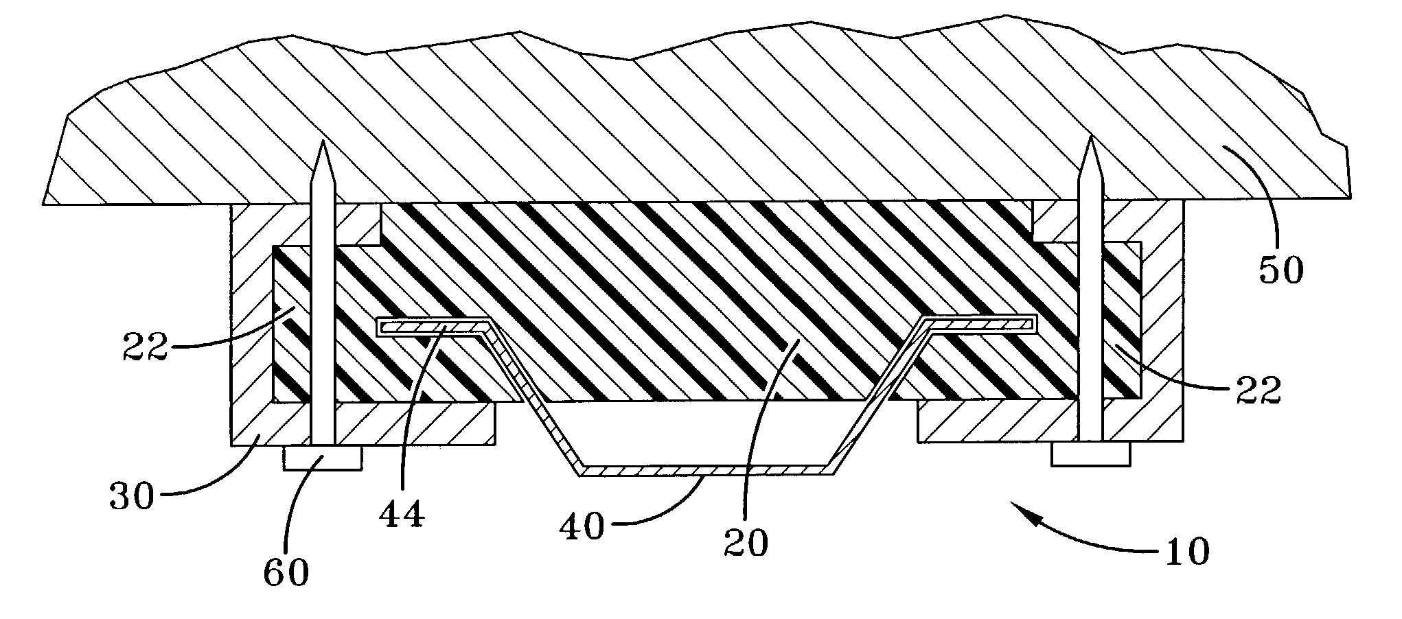
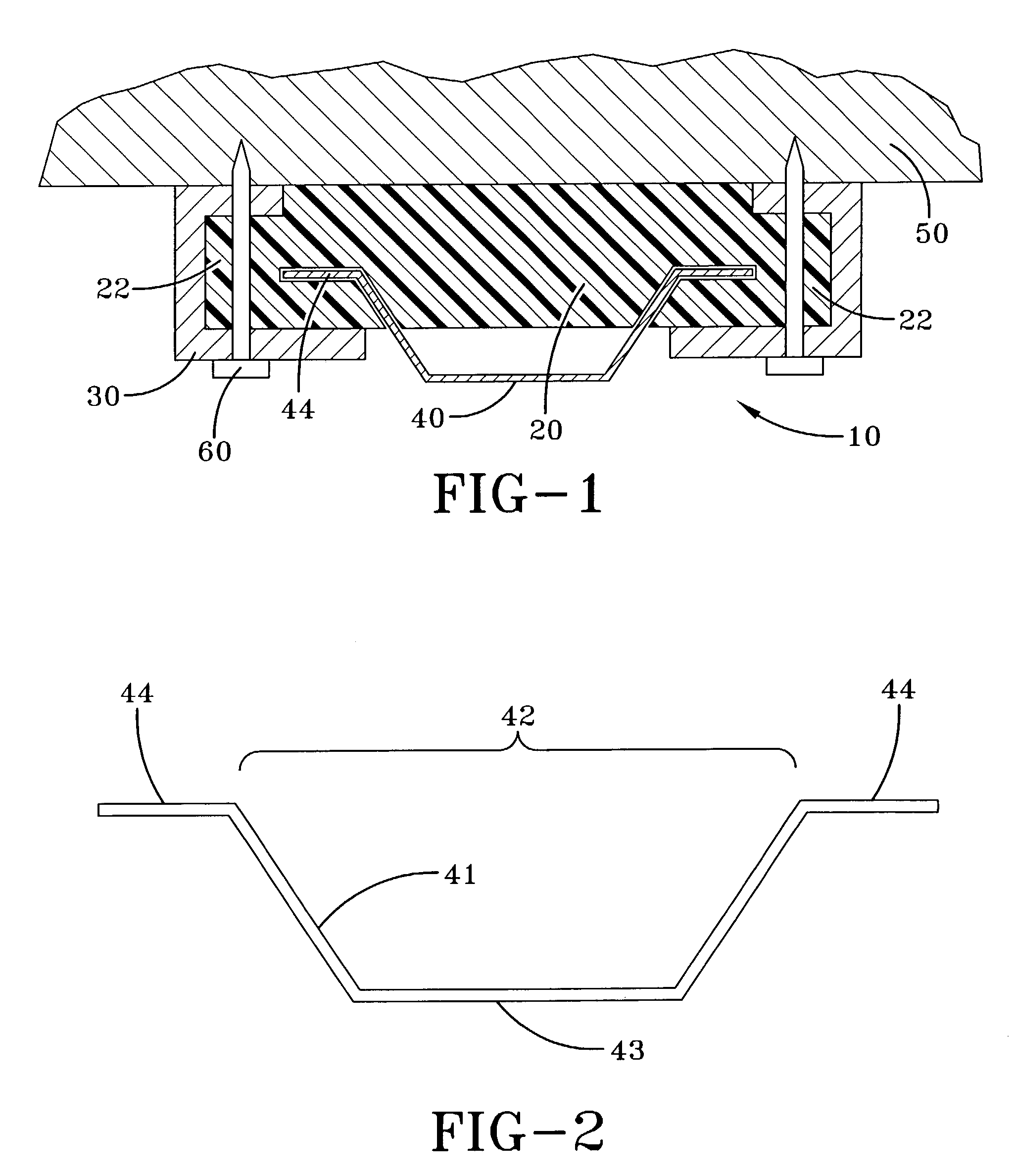
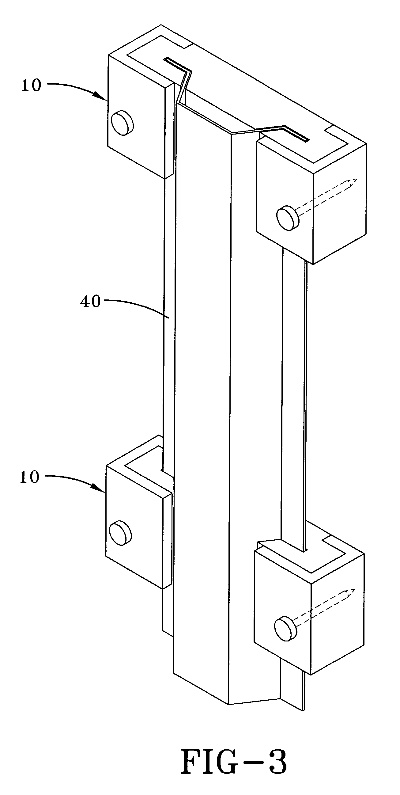
[0011]Various aspects of the invention are presented in FIGS. 1–3 which are not drawn to scale and in which like components are numbered alike. Referring now to FIGS. 1–2, according to an aspect of the invention, a vibration isolating mount 10 is used to mount a furring channel 40 to a mounting surface 50. The furring channel 40 comprises a channel portion 42 and two opposing furring channel flanges 44.

[0012]According to this aspect of the invention, the vibration isolating mount 10 comprises a vibration isolator 20 of a size and shape to fit snugly around the furring channel flanges 44. Direct contact between the furring channel and the vibration isolator more effectively dampens the vibration in the furring channel than do the prior art mounts with metal to metal contact between the mounting clip and the furring channel. The vibration isolator 20 has opposing vibration isolator flanges 22 extending away from the furring channel flanges 44. The vibration isolating mount 10 further ...


PUM


Abstract

The present invention comprises a vibration isolating mount used to mount a furring channel to a mounting surface wherein the furring channel comprises a channel portion and two opposing furring channel flanges. The vibration isolating mount comprises a vibration isolator of a size and shape to fit snugly around the furring channel flanges, wherein the vibration isolator has opposing flanges extending away from the furring channel flanges; and mounting brackets, wherein the mounting brackets wrap around the vibration isolator flanges, and wherein the mounting brackets are isolated from the furring channel by the vibration isolator.

Description

[0001]This application claims the benefit of U.S. Provisional Application No. 60 / 386,295, filed Jun. 5, 2002.BACKGROUND[0002]The present invention is in the field of noise and vibration control. More specifically this invention relates to an apparatus for isolating the structureborne vibration, and therefore the noise transferred from one part of a building to another.[0003]In many building applications, furring channels are used to attach one part of a building structure, for example wallboard or other sheet material, to another part of the building structure. Noise, transmitted structurally as vibration, is often transmitted from one part of the building to another through the furring channel connection points.[0004]Previously, furring channel mounting brackets were coated with a vibration absorbing material to reduce the noise transmitted through these mounting points. Although this does reduce the noise somewhat, these coated mounting brackets are expensive to manufacture.[0005]...

Claims


Application Information

Patent Timeline
Patent Type & Authority Patents(United States)
IPC IPC(8): F16M13/00F16F1/44
CPCF16F1/44
Inventor MEISEL, PAULSWYSGOOD, MATTHEW
Owner KINETICS NOISE CONTROL
Learn More