Pressure bleeding boot-type seal

a technology of boot-type seals and pressure bleeding, which is applied in the direction of engine seals, fluid actuated brakes, braking elements, etc., can solve the problems of burnt, melt, or other shortening of the useful life of the boot-type seal, and the buildup of fluid pressure within the boot-type seal

Inactive Publication Date: 2006-08-29
AKEBONO BRAKE
View PDF27 Cites 28 Cited by
  • Summary
  • Abstract
  • Description
  • Claims
  • Application Information

AI Technical Summary

Benefits of technology

[0005]In one preferred form, the present invention provides a boot-type seal for sealing a joint between a first surface and a second surface. The boot-type seal includes a seal having a first seal member, which is configured to sealingly engage the first surface, and a second seal member, which is configured to sealingly engage the second surface. The boot-type seal also includes a valve that is coupled to the seal. The valve is operable in a first condition, which inhibits fluid communication therethrough, and a second condition which permits fluid communication therethrough. The condition of the valve changes from the first condition to the second condition in response to a fluid pressure exerted on a side of the seal that exceeds a predetermined threshold pressure.

Problems solved by technology

Despite the widespread use of such boot-type seals, several drawbacks are known and thus, such boot-type seals are susceptible to improvement.
One such drawback concerns the buildup of fluid pressure within such boot-type seals.
In especially severe instances, it may be possible for the boot-type seal to expand and deleteriously contact another portion of the brake assembly, causing the boot-type seal to burn, melt, or otherwise undergo a shortening of its useful life as a result of thermal cycling at elevated temperatures.
If severe enough, such damage may lead to a failure of the boot-type seal through which dirt, debris, moisture and other contaminants may be transmitted.

Method used


Image

  • Pressure bleeding boot-type seal
  • Pressure bleeding boot-type seal
  • Pressure bleeding boot-type seal

Examples


Embodiment Construction

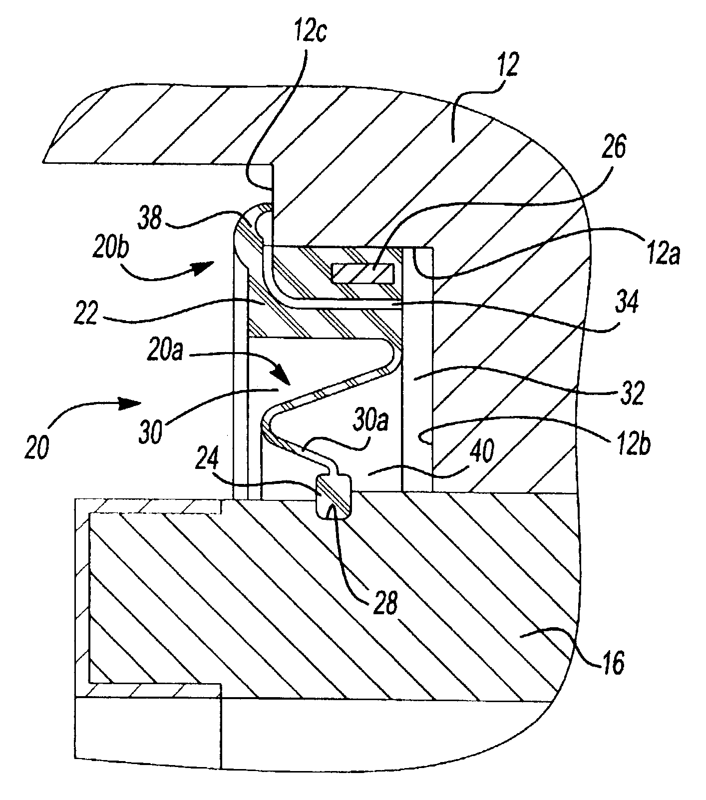
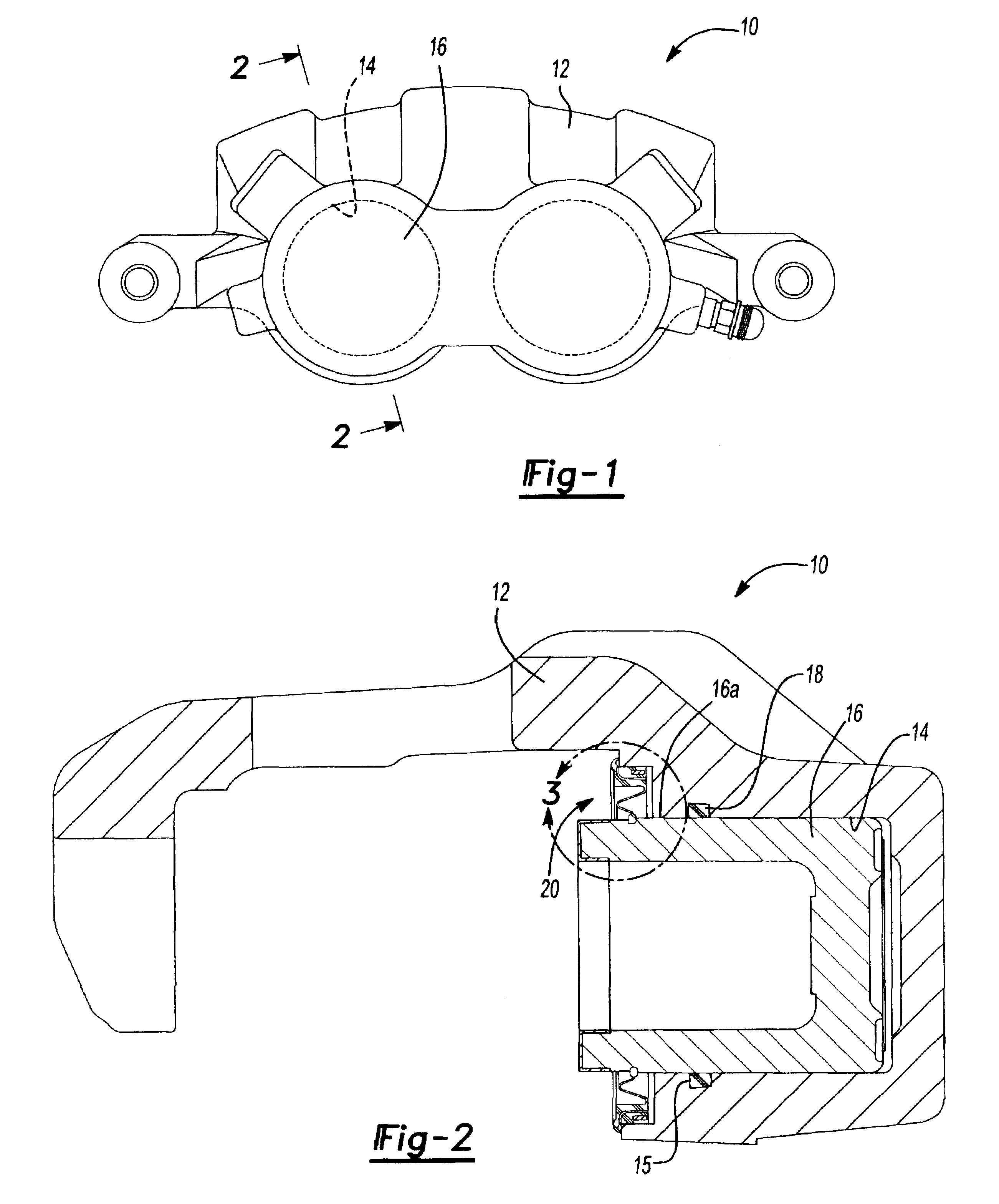
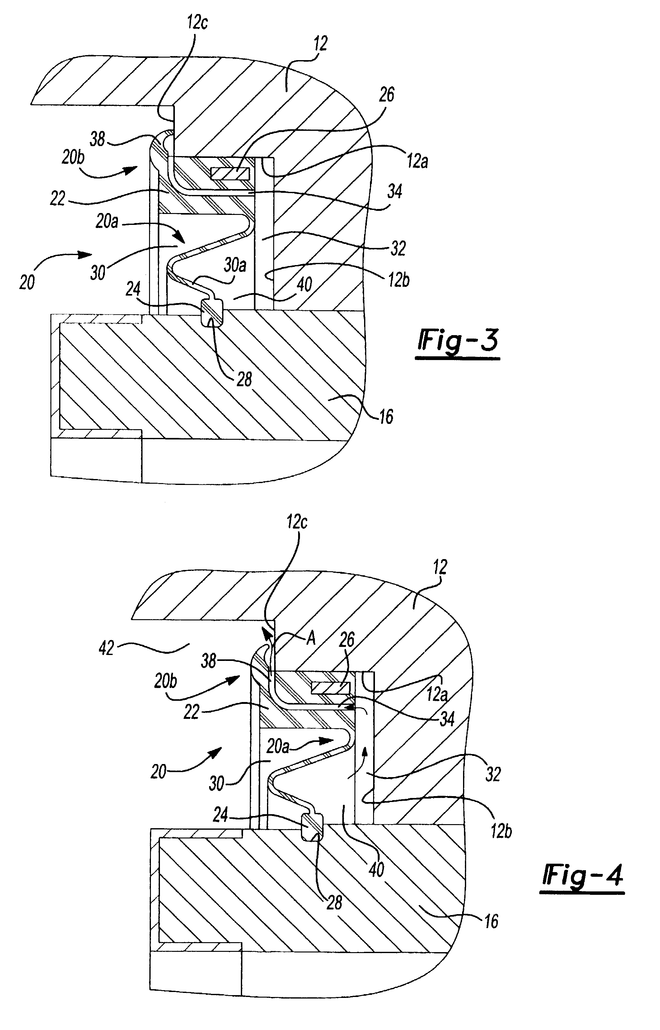
[0019]With reference to FIGS. 1 and 2 of the drawings, a brake assembly 10 is illustrated to include a caliper body 12, a caliper piston 16 and a boot-type seal 20 constructed in accordance with the teachings of the present invention. Although the brake assembly 10 is illustrated to be of a type that is commonly utilized in automotive vehicles, those skilled in the art will appreciate that the boot-type seal 20 of the present invention has other uses. Accordingly, those skilled in the art will appreciate that the example provided herein should not be interpreted as limiting the scope of the present invention in any way.

[0020]In the example provided, the caliper body 12 conventionally includes a piston bore 14, which is sized to slidingly receive the caliper piston 16, and an annular seal groove 15, which is sized to receive an annular high-pressure piston seal 18. The high-pressure piston seal 18 sealingly engages both the caliper body 12 and the caliper piston 16 in a conventional ...


PUM


Abstract

A boot-type seal having a seal and a valve. The seal has a first seal member, which is configured to sealingly engage a first surface, and a second seal member, which is configured to sealingly engage a second surface. The valve is coupled to the seal and is operable in a first condition, which inhibits fluid communication therethrough, and a second condition, which permits fluid communication therethrough. The condition of the valve changes from the first condition to the second condition in response to a fluid pressure exerted on a side of the seal that exceeds a predetermined threshold pressure. A brake assembly that incorporates the boot-type seal is also provided.

Description

FIELD OF THE INVENTION[0001]The present invention generally relates to boot-type seals and more particularly to a pressure-bleeding boot-type seal that is especially suited for use in a brake assembly.BACKGROUND OF THE INVENTION[0002]A typical brake assembly for a motor vehicle includes a caliper assembly and one or more brake pads. The caliper assembly includes a frame or body, which is mounted to the structure of the vehicle and a caliper piston. The caliper piston is movably mounted to the caliper body so as to be selectively engagable with the brake pads to cause the brake pads to frictionally engage an element, such as a vehicle rotor, to thereby slow or stop the vehicle.[0003]The caliper body includes a piston bore into which the piston is received. A boot-type seal is typically employed to seal around the perimeter of both the piston bore and the caliper piston to inhibit moisture, dirt, debris and other contaminants from entering the piston bore and potentially damaging the ...

Claims


Application Information

Patent Timeline
Patent Type & Authority Patents(United States)
IPC IPC(8): F16D55/18F16D65/18F16J3/04
CPCF16J3/046
Inventor BARRETT, SEANNISHIMURA, SEIJIMATSUMOTO, TAKASHI
Owner AKEBONO BRAKE
Why Eureka
Try Eureka