Hanger rack for hand tools

Inactive Publication Date: 2006-09-05
KAO JUI CHIEN
View PDF9 Cites 31 Cited by
  • Summary
  • Abstract
  • Description
  • Claims
  • Application Information

AI Technical Summary

Problems solved by technology

However, the fixture pieces are securely mounted on the bar and spaces between the fixture pieces cannot be adjusted according to sizes of hand tools.

Method used


Image

  • Hanger rack for hand tools
  • Hanger rack for hand tools
  • Hanger rack for hand tools

Examples


Embodiment Construction

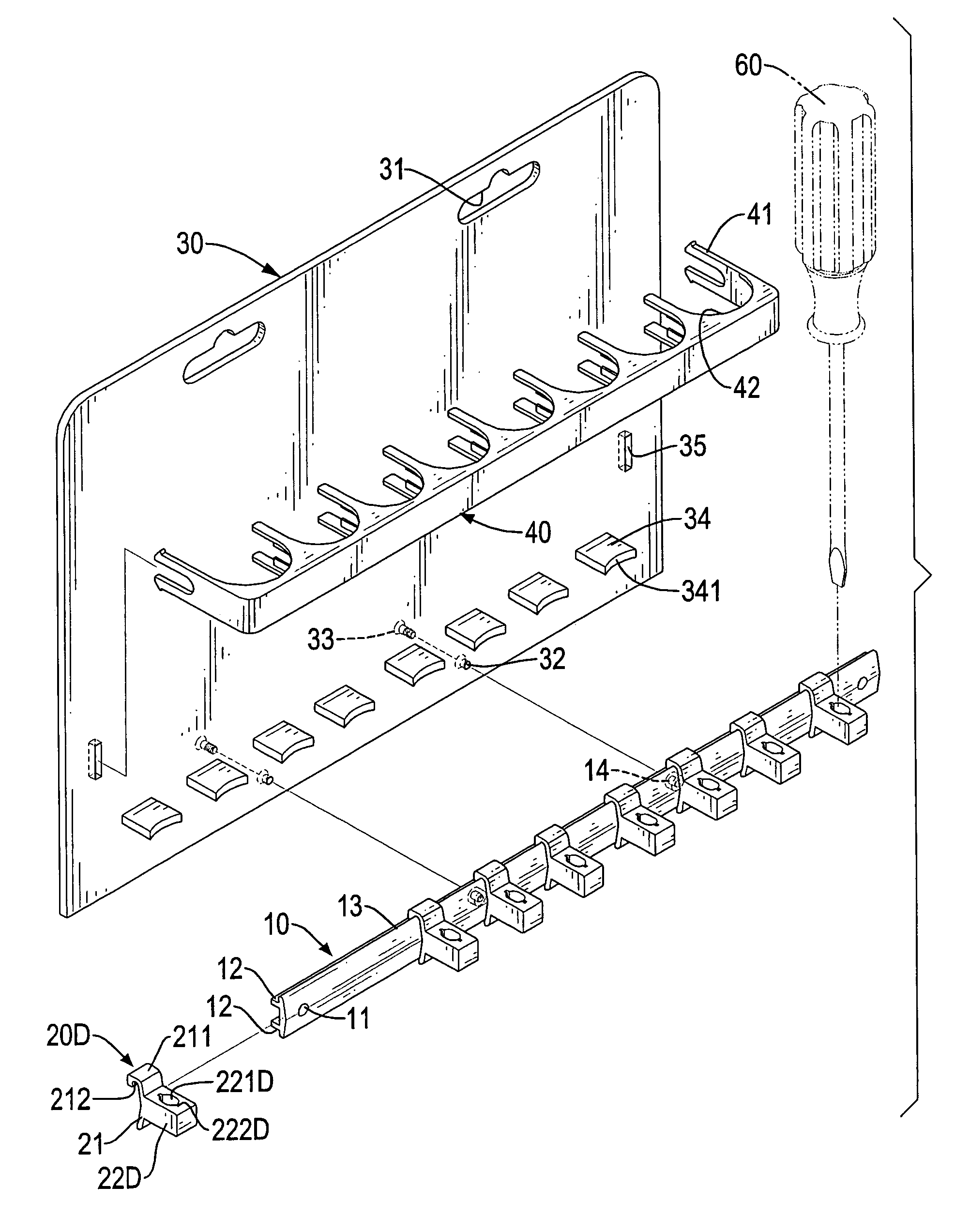
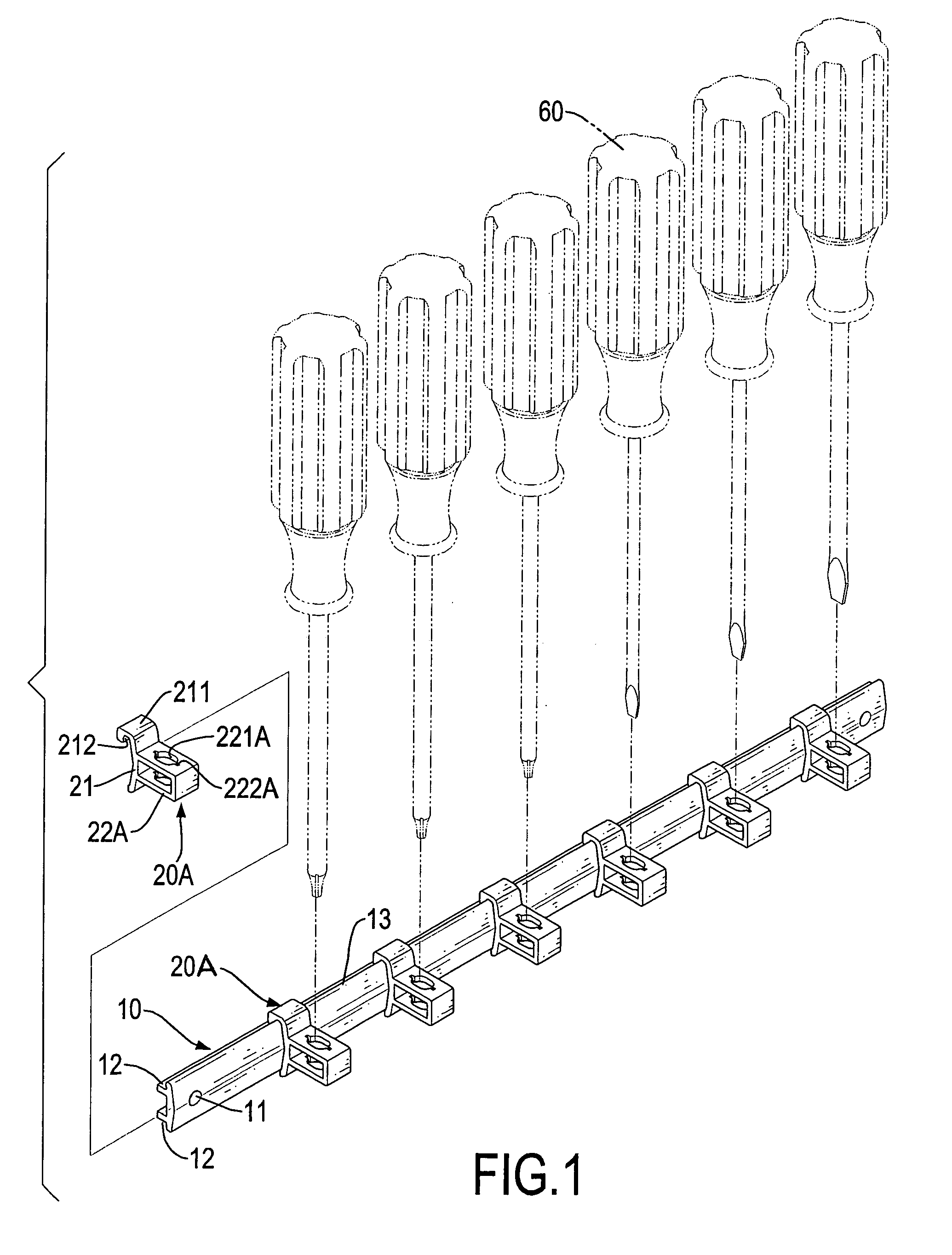
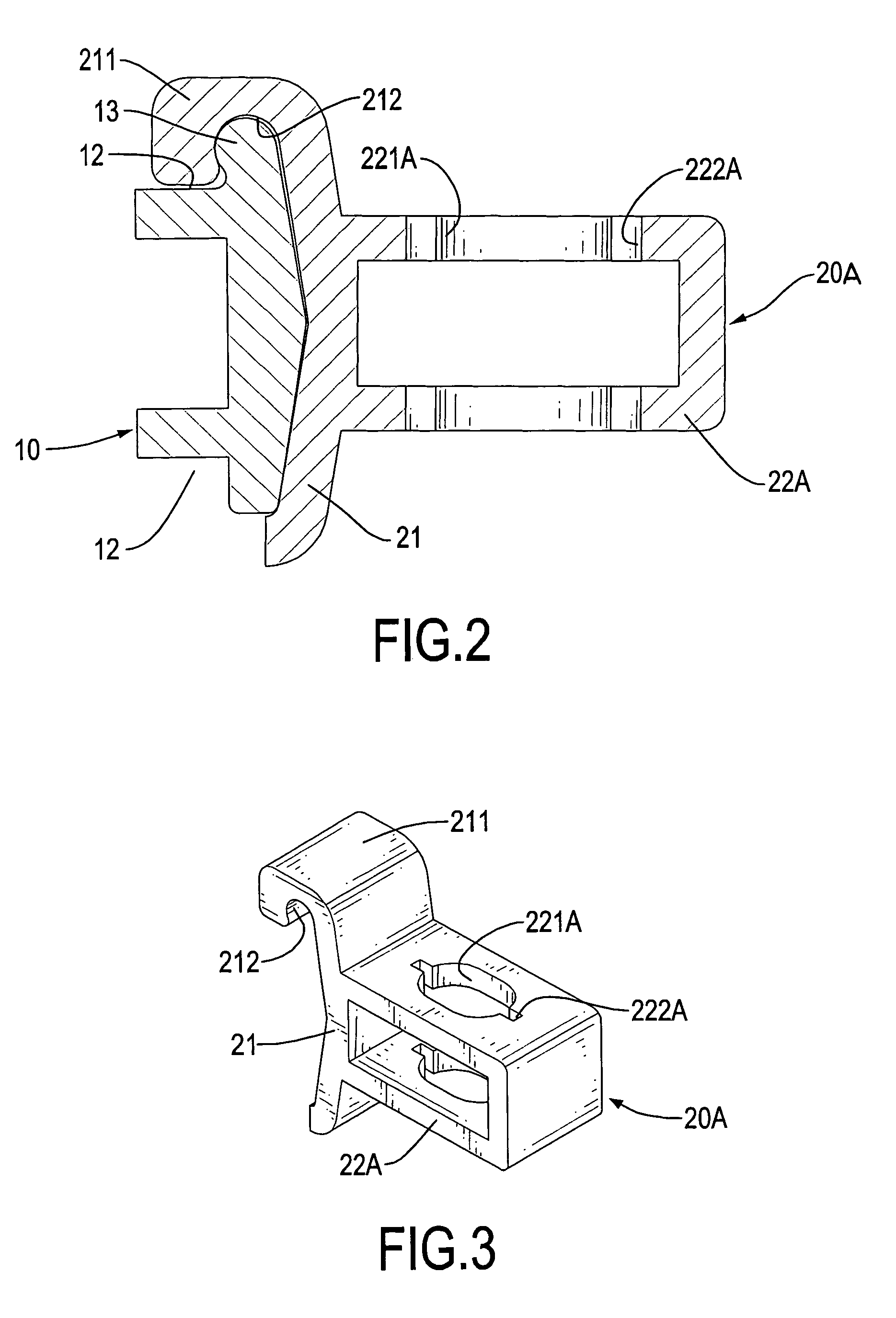
[0018]With reference to FIGS. 1–3, a hanger rack in accordance with the present invention has a bar (10) and multiple fixture pieces (20A) movably provided on the bar (10). The bar (10) has a substantially π-like cross section rotated 90 degrees in that a longitudinal strip has a front face and a rear face, with two parallel legs extending perpendicularly along the longitudinal strip and on the rear face. Two parallel channels (12) are respectively defined in an upper face and lower face of the legs. A longitudinal ridge is formed at a front face of the longitudinal strip. A rail (13) with a round edge is formed at an upper side of the bar (10). Two fastening members are respectively formed at two ends of the bar (10). In a preferred embodiment, the fastening members are two holes (11) respectively defined at two ends of the bar (10) for installing the bar (10) by fasteners being extended through the holes (11) and into a support surface such as a wall (not shown).

[0019]Referring to...


PUM


Abstract

A hanger rack for hand tools includes a bar having a rail formed at an upper side of the bar. Multiple fixture pieces are movably mounted on the bar. Each fixture piece has a seat with a hook slidably attached to the rail and a hanging member laterally extending from the seat for attaching with a hand tool. Whereby, the fixture pieces are slidable along the bar, spaces between two adjacent fixture pieces can be adjusted according to the sizes of the hand tools such as screwdrivers.

Description

BACKGROUND OF THE INVENTION[0001]1. Field of the Invention[0002]The present invention relates to a hanger rack for hand tools, and more particularly to a hanger rack of which fixture pieces can be adjusted according to sizes of hand tools.[0003]2. Description of Related Art[0004]A conventional hanger rack for hand tools generally includes a bar and multiple fixture pieces. However, the fixture pieces are securely mounted on the bar and spaces between the fixture pieces cannot be adjusted according to sizes of hand tools.[0005]Therefore, the invention provides a hanger rack for hand tools to mitigate or obviate the aforementioned problems.SUMMARY OF THE INVENTION[0006]The main objective of the present invention is to provide a hanger rack of which fixture pieces are adjustable according to sizes of hand tools.[0007]Other objectives, advantages and novel features of the invention will become more apparent from the following detailed description when taken in conjunction with the accom...

Claims


Application Information

Patent Timeline
IPC IPC(8): A47F7/00
CPCB25H3/04A47F5/0807
Inventor KAO, JUI-CHIEN
Owner KAO JUI CHIEN
Why Eureka
Try Eureka