Cross link system

a cross-linking and link technology, applied in the field of orthopaedic surgery, can solve the problems of deformation or failure, no hooks to prevent,

Active Publication Date: 2006-09-12
ATLAS SPINE
View PDF19 Cites 73 Cited by
  • Summary
  • Abstract
  • Description
  • Claims
  • Application Information

AI Technical Summary

Problems solved by technology

The opposing sides of the hook resist the shear forces however, there is nothing to prevent the hooks from, “walking,” along the spinal rods in response to unequal movement of each spinal rod.
The ends of the telescoped rods act directly on the shaft of the set screw in shear which may result in deformation or failure.

Method used


Image

  • Cross link system
  • Cross link system
  • Cross link system

Examples


Embodiment Construction

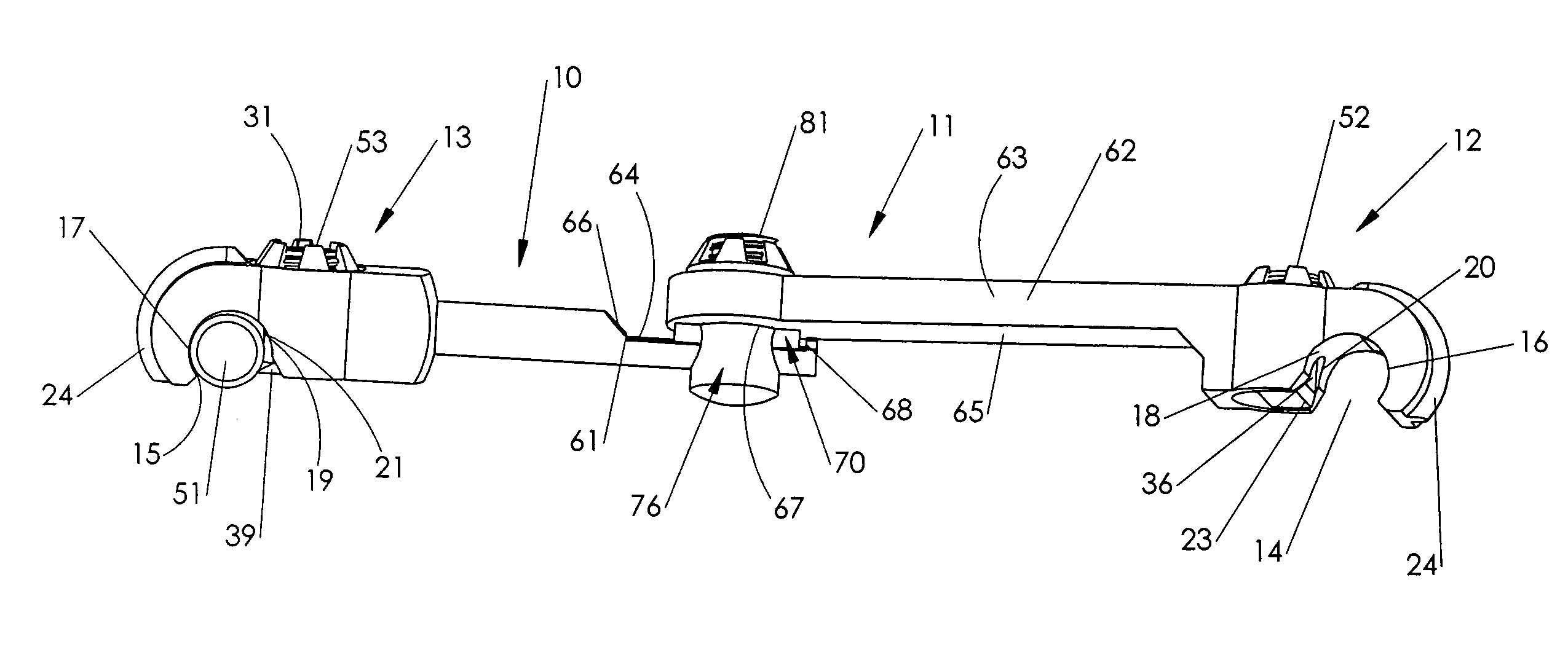
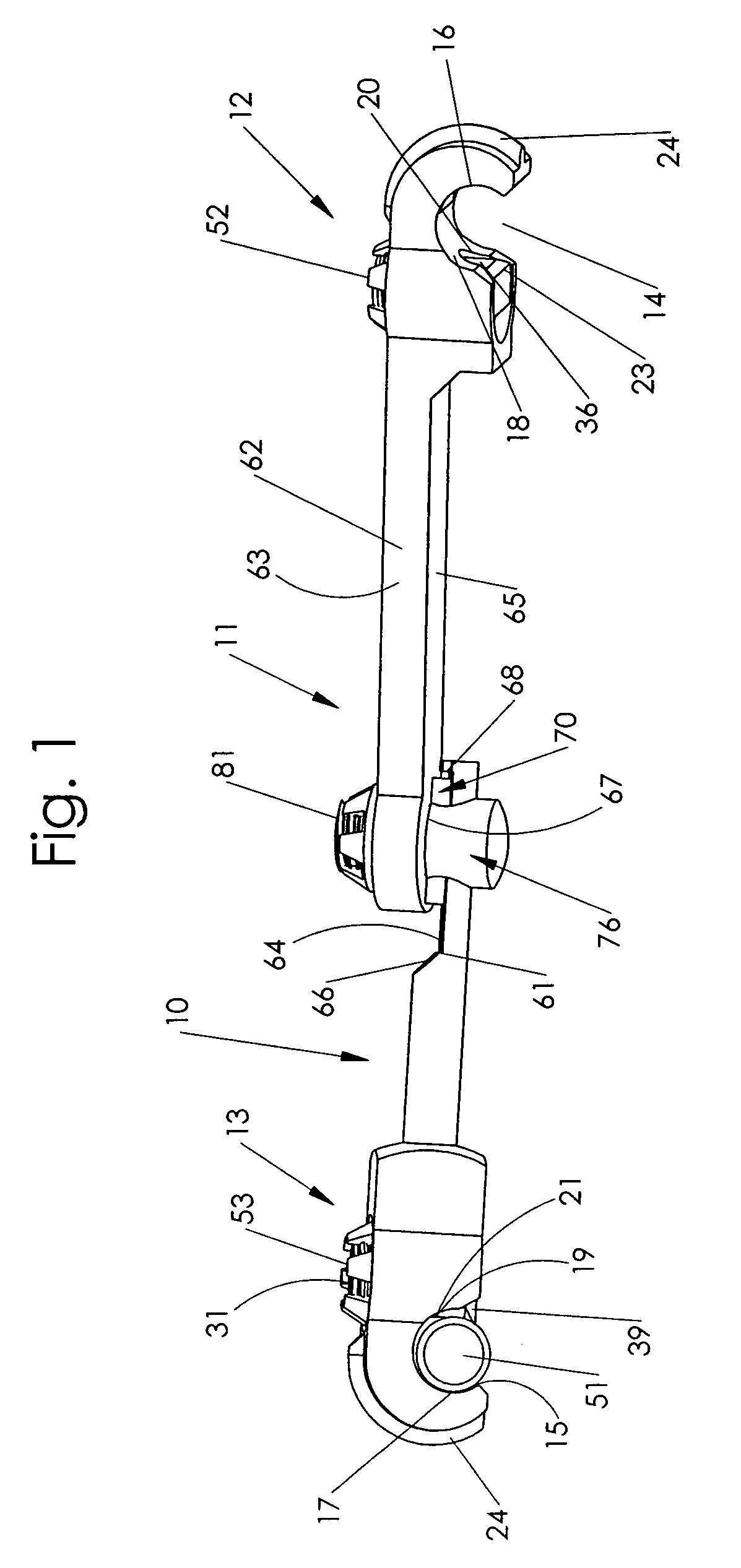
[0021]The link system 10 has a bar 11 which extends between two generally parallel spinal rods, only rod 51 is shown. The bar 11 has two connectors 12 and 13 that are placed over the rods to hold the cross link in place along the length of the rods. Connector 12 has a groove 14 which is transverse to the longitudinal axis of the bar 11. The groove 14 has upstanding sides 16 and 18. A channel 20 is formed in upstanding wall 18. The channel 20 is a discontinuity in the side wall 18 and exposes a portion of the actuator arm 23. The upstanding wall 16 is reinforced with a thickened ridge 24 along the outer surface of the groove 14.

[0022]Connector 13 has a groove 15 which is transverse to the longitudinal axis of the bar 11. The groove 15 has upstanding sides 17 and 19. A channel 21 is formed in upstanding wall 19. The channel 21 is a discontinuity in the side wall 19 and exposes a portion of the actuator arm 23. The upstanding wall 17 is reinforced with a thickened ridge along the outer...


PUM


Abstract

A cross link system provides stability to spinal rods by maintaining a set distance between the rods. The cross link has a bar with connectors on each end formed with grooves that engage each of the spinal rods. Each of the connectors has a cam that can be manipulated to obstruct the groove and provide a friction fit between the spinal rod and the cross link. The cams have locking nuts that prevent disengagement of the cam and rod. The bar has two shafts interconnected by a bifurcated pin with upstanding ends, a piston is located between the upstanding ends and diverts shear forces along the longitudinal axis of the bar.

Description

BACKGROUND OF THE INVENTION[0001]1. Field of the Invention[0002]This invention relates to the field of orthopedic surgery and, particularly, to a cross link attachable to a pair of spinal rods to stabilize relative movement between the rods during body movements.[0003]2. Description of the Prior Art[0004]The use of spinal rods is conventional for correction of spinal trauma or conditions, such as curvature of the spine. Generally parallel rods are attached to the spine by pedicle screws for support or correction of abnormalities. During normal activities, the spine is subjected to bending and twisting motions which affect the relative position of the spinal rods. In some cases, the rods are cross braced for additional stability. The cross link is attached to each of the spinal rods and provides fixed spacing between the rods. The resultant forces acting on the cross link are primarily in shear along the longitudinal axis of the cross link.[0005]Estes, U.S. Pat. No. 5,693,053, teache...

Claims


Application Information

Patent Timeline
Patent Type & Authority Patents(United States)
IPC IPC(8): A61B17/56A61B17/70
CPCA61B17/7052
Inventor BAYNHAM, BRET O.BAYNHAM, G. CLAYBAYNHAM, MATTHEW G.CAMPBELL, DAVID R.
Owner ATLAS SPINE
Why Eureka
Try Eureka