Dynamic spinal stabilization device

a spinal stabilization device and dynamic technology, applied in the field of spinal vertebrae connections, can solve the problems of inability to properly align vertebrae, inability to properly articulate or align vertebrae, and damage to the anterior elements of the spine, so as to preserve physiological spinal movement, stabilize the vertebrae, and limit rotation

Inactive Publication Date: 2008-02-07
IMPLICITO DANTE
View PDF12 Cites 98 Cited by
  • Summary
  • Abstract
  • Description
  • Claims
  • Application Information

AI Technical Summary

Benefits of technology

[0006]The present invention regards linking spinal vertebrae to stabilize vertebrae and preserve physiological spinal movement. Preferably, the crossover connector simulates the natural functions of intact facet joints, such as accommodating flexion and extension, and limiting rotation. The various systems, methods, devices, and kits that embody the invention may employ a vertebrae crossover connector to link or otherwise connect vertebrae in a spinal column. These connectors may be positioned during a procedure between anchors inserted in vertebrae such that they crossover the spinal canal. In certain embodiments, each crossover connector may include one or more stretchable couplings that can stretch and resist tensile loads placed on them by the anchors coupled to the spinal column when the anchors move apart from one another. The crossover connector may also include a main body that may bear compressive loads placed on the connector by these same anchors when they move towards one another. The main body of one or more crossover connectors may be linear, bowed and may even form an “X” shape in some instances. The X shape may be formed by the body itself as well as when multiple connectors are surgically placed across one another between vertebrae anchors. There are numerous other configurations of the crossover connector and the components that comprise it.
[0007]The present invention may be embodied in a spinal stabilization kit. This kit may include: (a) a crossover connector having a main body and one or more stretchable couplings; (b) a plurality of spacers that may be used to change the length and configuration of the main body; and (c) a plurality of screws that may be used to an

Problems solved by technology

Through disease or injury, the posterior elements of the spine, including the facet joints of one or more vertebrae, can become damaged such that the vertebrae no longer articulate or properly align with each other

Method used


Image

  • Dynamic spinal stabilization device
  • Dynamic spinal stabilization device
  • Dynamic spinal stabilization device

Examples


Embodiment Construction

[0026]In embodiments of the present invention, crossover connectors may be employed to stabilize the spinal column and to facilitate motion of the spinal column. The invention may be employed after the removal of posterior portions of vertebrae and / or after some trauma or deterioration has occurred to the vertebrae. The invention may be used at other times and in other clinical situations as well.

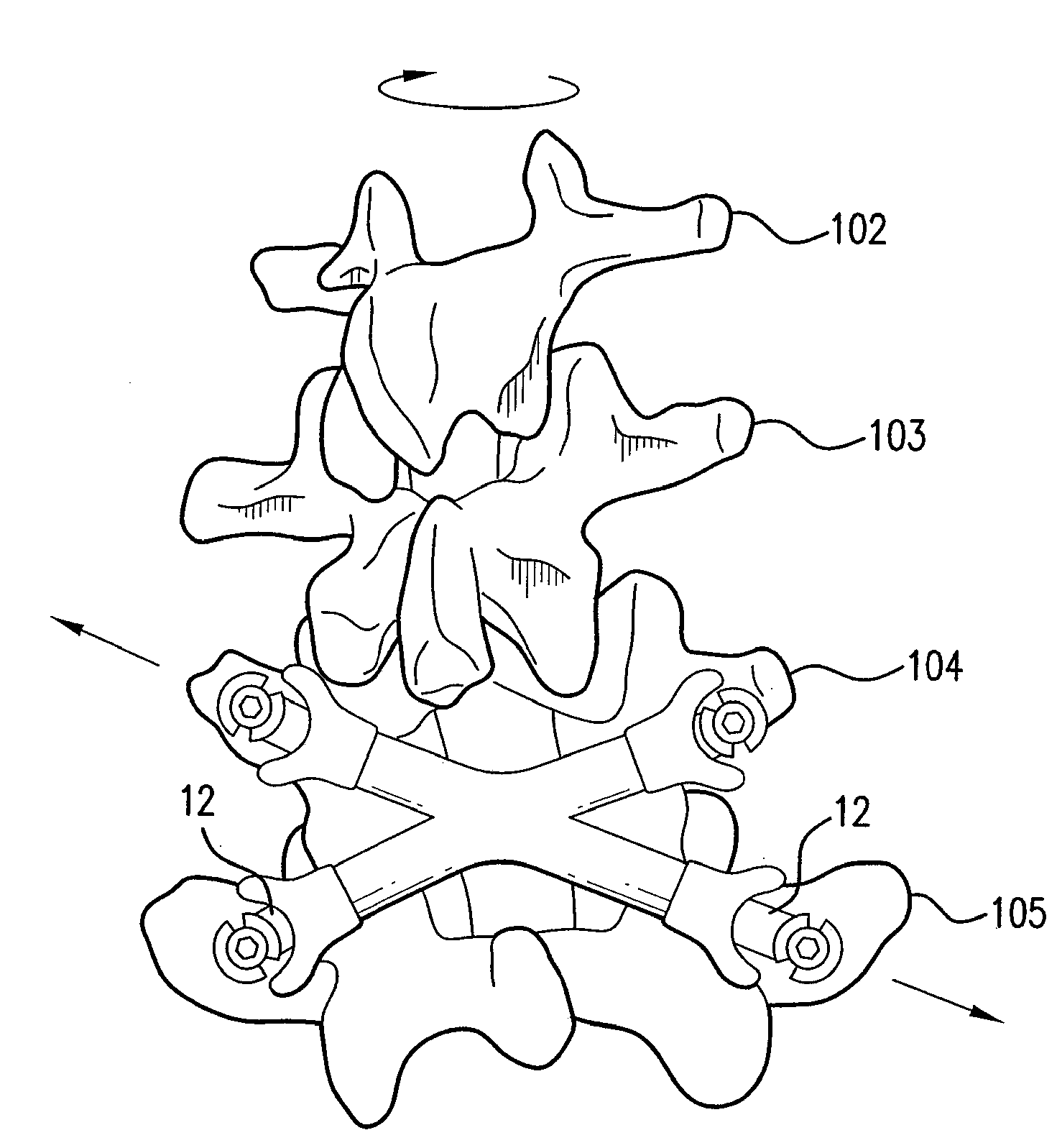
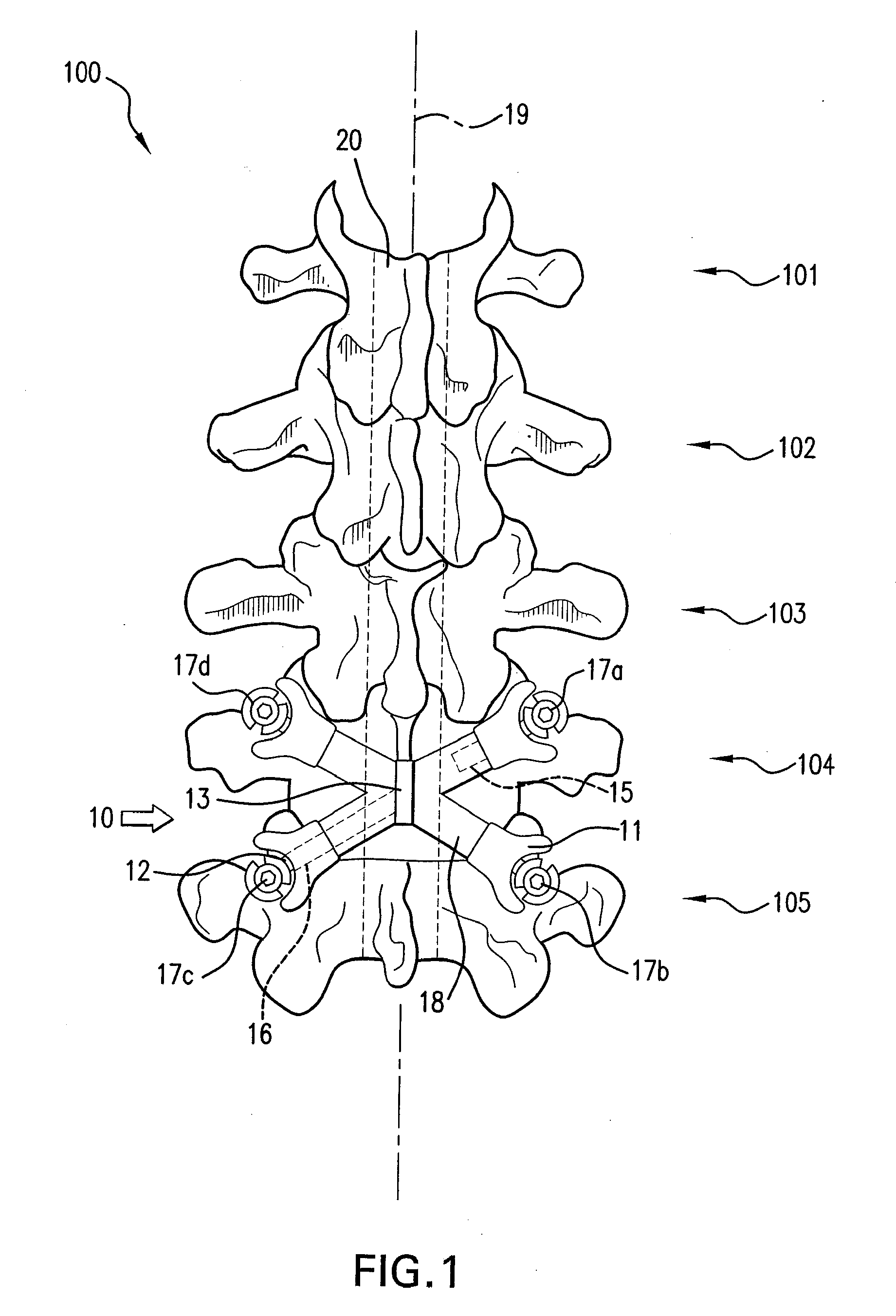
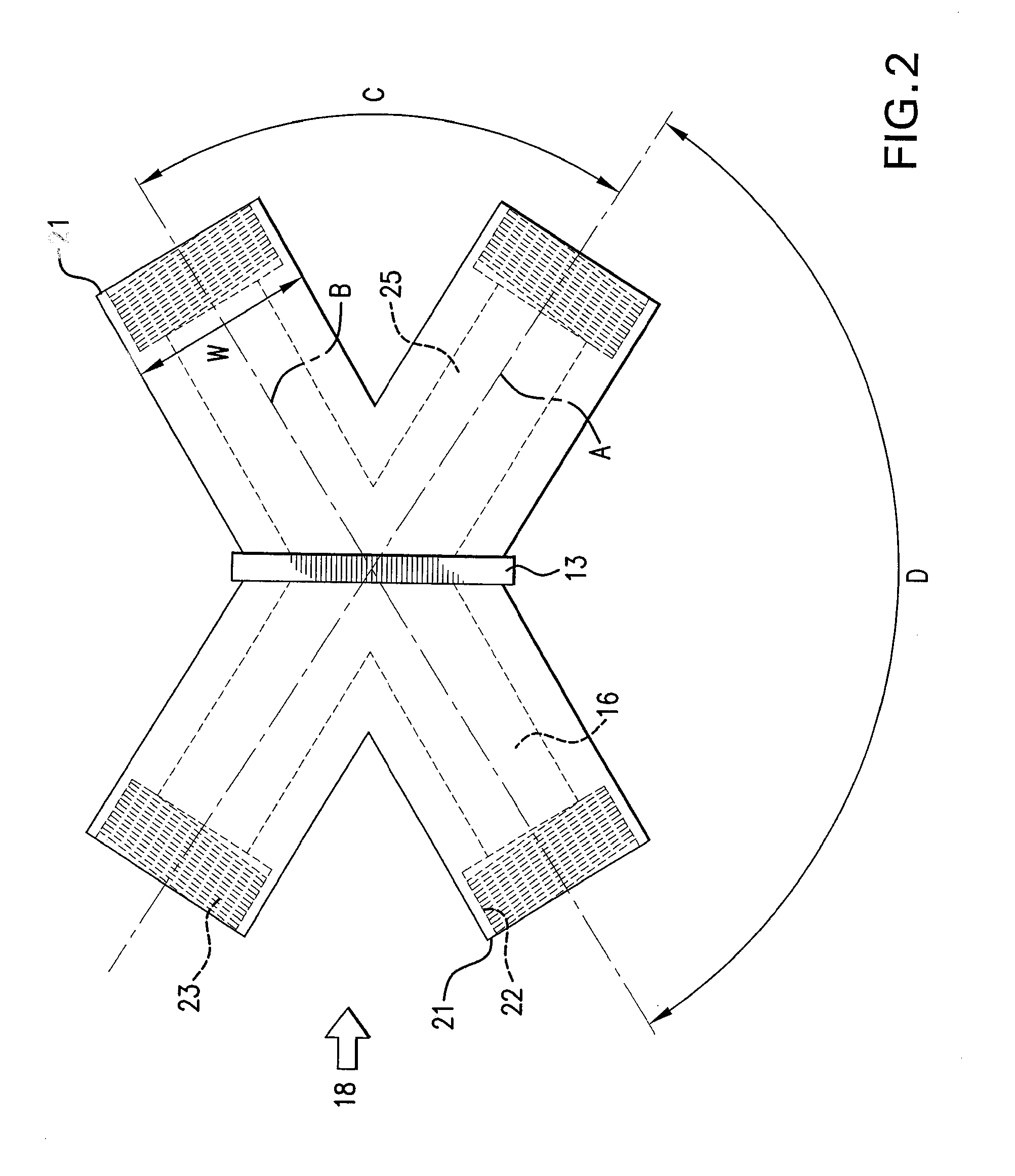
[0027]FIG. 1 illustrates an example of the present invention. There, a crossover connector 10 has been installed after removal of posterior portions of adjacent spinal vertebrae from the lumbar region of the spine. Visible in FIG. 1 is a portion of the spinal column 100 with five lumbar vertebrae numbered 101 through 105, four anchors numbered 17a to 17d, a crossover connector 10, and the spinal canal 20. The crossover connector 10 is shown with a main body 18, stretchable coupling 12, spacers 11, coupling passage 16, and central fin 13. The coupling passage 16 is present in each of the arm...


PUM


Abstract

The present invention regards linking spinal vertebrae to provide support and alignment of one or more vertebrae. The various systems, methods, devices and kits that embody the invention may employ a vertebrae crossover connector to link or otherwise connect one or more vertebrae in a column of vertebrae. These connectors may be positioned between anchors added to the vertebrae and may span the center of the spinal column when the connectors are positioned between the anchors. In certain embodiments each crossover connector may include one or more stretchable couplings that can stretch and resist tensile loads placed on them when the spinal column is stationary and in various ranges of motion. The crossover connector may also include a main body that may resist compressive loads placed on the crossover connector when the spinal column is in various ranges of motion in certain positions.

Description

FIELD OF THE INVENTION[0001]The present invention relates to spinal vertebrae connections. More specifically, the present invention relates to methods, systems, apparatus, and kits that may function to stabilize vertebrae of the spine.BACKGROUND OF THE INVENTION[0002]The human spinal column consists of a series of thirty-three stacked vertebrae. Each vertebrae is separated by a disc and includes a vertebral body having several posterior facing structures. These posterior structures include pedicles, lamina, articular processes, and spinous process. The articular processes, which function as pivoting points between vertebrae, include left and right superior and inferior processes. The superior and inferior processes of adjacent vertebrae mate with each other to form joints called facet joints. In a typical pair of vertebrae, the inferior articular facet of an upper vertebrae mates with the superior articular facet of the vertebra below to form a facet joint.[0003]The facet joints of ...

Claims


Application Information

Patent Timeline
IPC IPC(8): A61B17/58A61B17/56
CPCA61B17/7005A61B17/7008A61B2017/7073A61B17/7031A61B17/7011
Inventor IMPLICITO, DANTE
Owner IMPLICITO DANTE
Why Eureka
Try Eureka