Spinal disc implant with complimentary members between vertebral engaging plates

a technology of spine disc and engaging plate, which is applied in the field of spine disc implants, can solve the problems of destabilizing bone and affecting surrounding structures, pain and/or nerve damage, and altering the natural spacing between adjacent vertebrae, so as to reduce noise

Active Publication Date: 2011-03-22
ZIMMER BIOMET SPINE INC
View PDF38 Cites 85 Cited by
  • Summary
  • Abstract
  • Description
  • Claims
  • Application Information

AI Technical Summary

Benefits of technology

[0008]In certain embodiments, a disc implant may be used to stabilize vertebrae of a human spine while allowing normal movement of the vertebrae relative to each other. An artificial disc implant may replace a diseased or defective intervertebral disc. An artificial disc implant may be easy to install with only minimal intrusion to adjacent tissue and muscle. A disc implant may introduce minimal risk of dural damage or neural damage during installation and use.
[0010]In some embodiments, an engaging plate may include a recess complementary to a portion of a member. In certain embodiments, an engaging plate may include slots. The slots may be dovetailed. The slots may be complementary to a portion of an instrument used to insert engaging plates between vertebrae. In some embodiments, slots may be formed at an angle relative to an anterior-posterior axis of an engaging plate. In some embodiments, an angular orientation of a recess may correspond to an angle of slots in an engaging plate. Angulation of the slots may allow insertion of a disc implant using a modified (e.g., angulated) anterior approach. A modified anterior approach may facilitate retraction of blood vessels above the L5 vertebrae.
[0011]In certain embodiments, an engaging plate may include one or more coupling projections. One or more coupling projections may penetrate a vertebral surface. In some embodiments, a coupling projection may be positioned in a recess formed in a vertebral surface. Once positioned in the vertebra, the coupling projection may inhibit movement of an engaging plate relative to the vertebra.
[0018]An inserter may be used to position engaging plates between two vertebrae. A distractor may be positioned between the engaging plates to establish a desired separation distance between the engaging plates. One or more members may be guided through a body of the distractor and into the space between the engaging plates. In some embodiments, members may be guided through a body of a distractor with a pusher. The pusher may maintain the position of the members when a distractor is removed from the inserter.
[0019]In certain embodiments, trial endplates, members and engaging plates may be formed from various materials including plastics, ceramics, polymers, composites and metals. Materials may be chosen based on factors including, but not limited to, durability, biocompatibility, galling characteristics, mechanical strength and / or wear properties. In some embodiments, radiological markers may be used in combination with materials that are “invisible” to radiological techniques. In certain embodiments, steps may be taken to adjust a coefficient of friction of materials chosen to form members (e.g., surfaces may be polished or roughened). In other embodiments, surfaces of engaging plates and / or members may be coated to reduce noise created by contact of a member with an engaging plate and / or another member.

Problems solved by technology

Degeneration may destabilize bone and affect surrounding structures.
For example, destabilization of a spine may result in alteration of a natural spacing between adjacent vertebrae.
Pressure applied to the nerves may cause pain and / or nerve damage.
Dissection and retraction of soft tissue may cause trauma to the soft tissue and extend recovery time.
Minimally invasive procedures and systems may reduce recovery time as well as trauma to the soft tissue surrounding a stabilization site.
In some embodiments, a range of motion of one engaging plate relative to another engaging plate may be limited.

Method used


Image

  • Spinal disc implant with complimentary members between vertebral engaging plates
  • Spinal disc implant with complimentary members between vertebral engaging plates
  • Spinal disc implant with complimentary members between vertebral engaging plates

Examples


Embodiment Construction

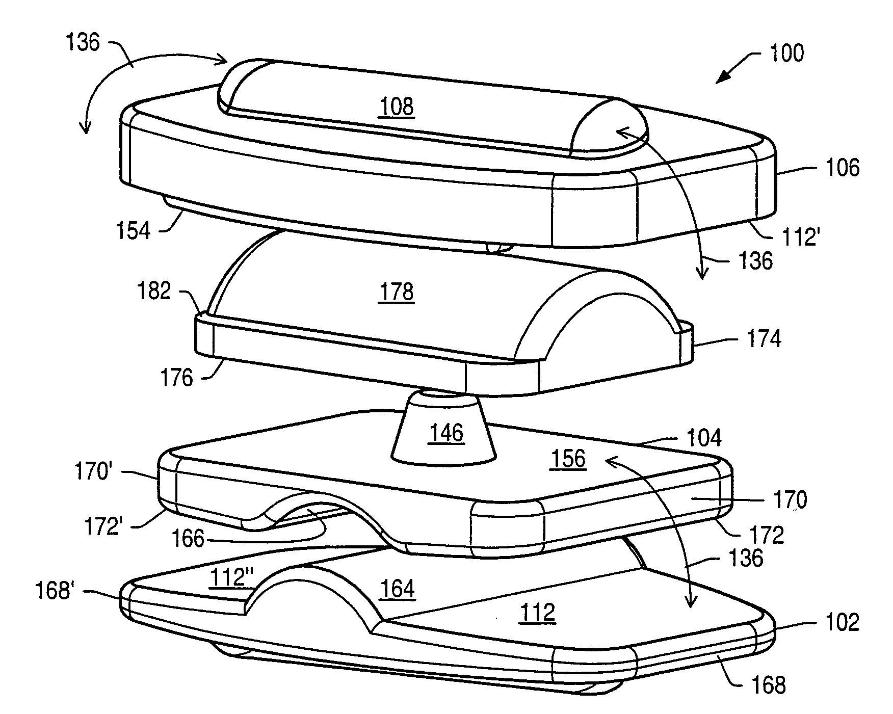
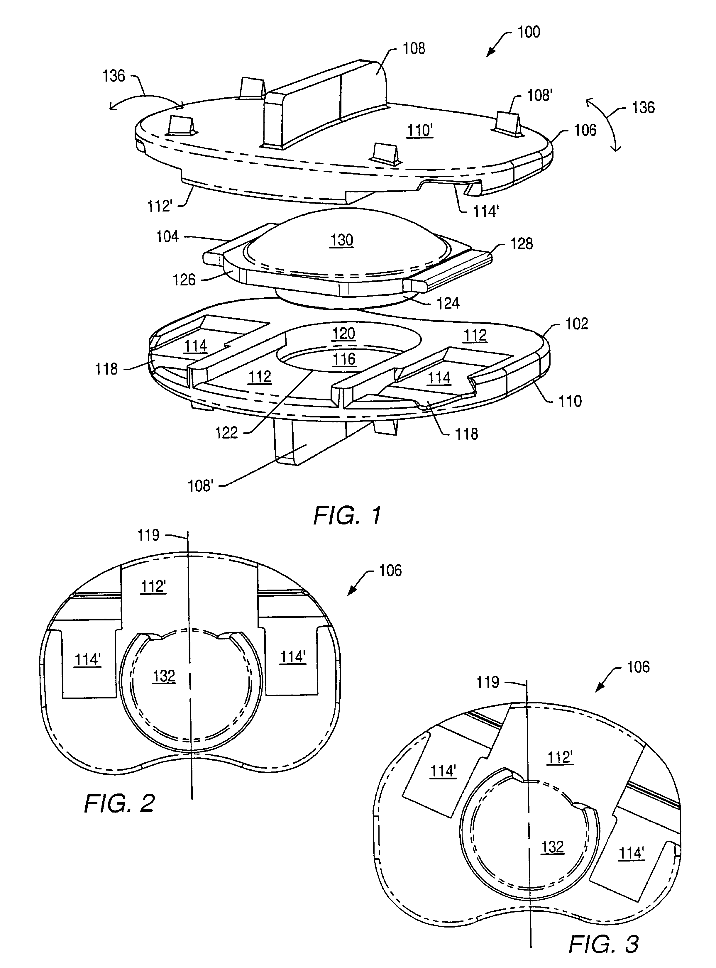
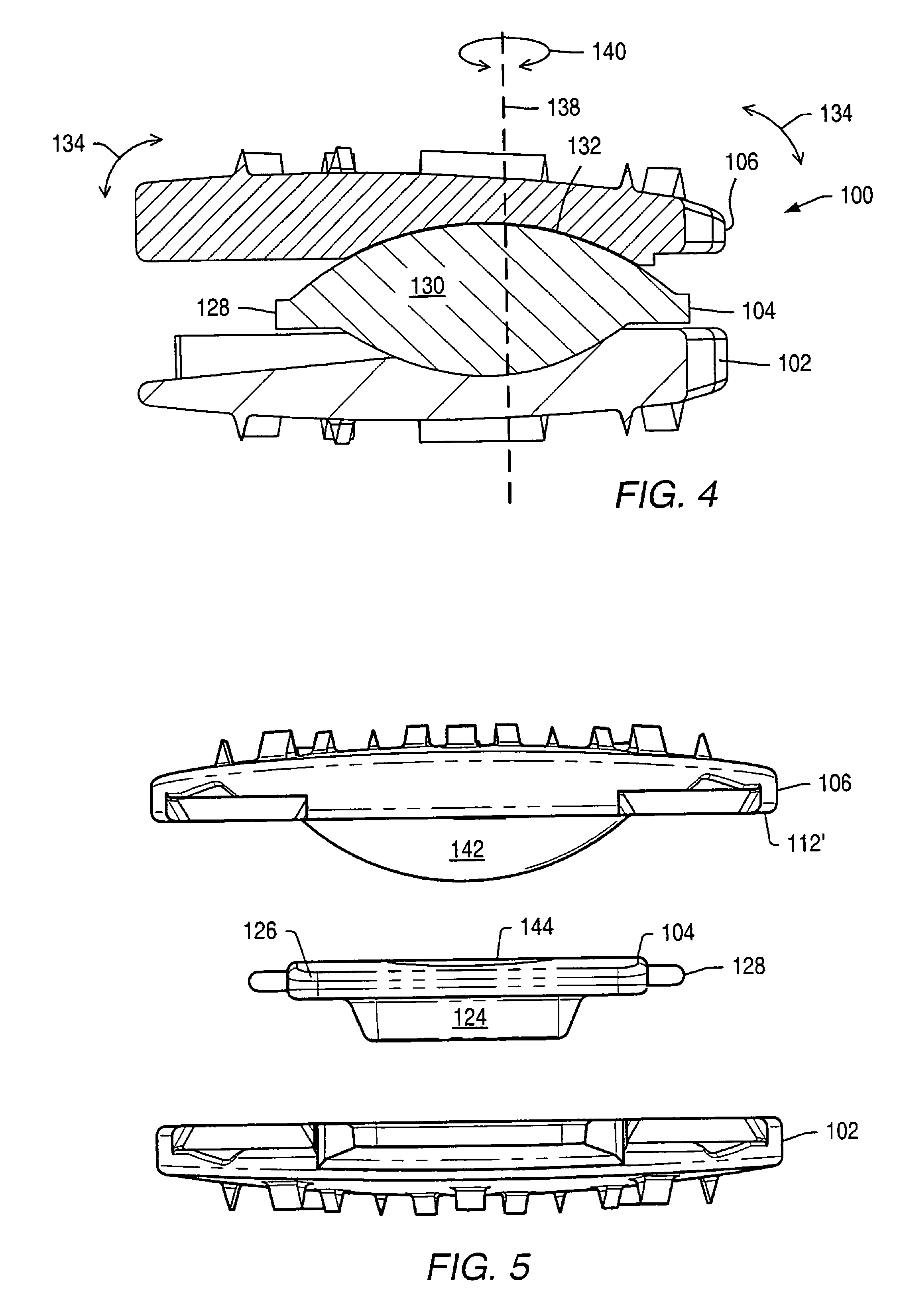
[0061]An intervertebral disc implant may be used to stabilize a portion of the spine. The artificial intervertebral disc implant may replace all or a portion of an intervertebral disc that requires replacement due to degeneration from natural wear, trauma or disease. The artificial intervertebral disc may restore the normal separation distance between the vertebrae and allow normal movement and flexibility of the spine.

[0062]Disc implants may allow movement of adjacent vertebrae relative to each other in ranges associated with normal limits for human vertebrae. Disc implants may allow axial rotation, axial compression and lateral and / or anteroposterior movement. In a human spine, axial rotation may include rotation of about 0.1° to about 3° about a longitudinal axis of the spine. An axis of rotation between vertebrae may be off-center due to the fibrocartilaginous nature of an intervertebral disc. An axis of rotation between two vertebrae may be located posterior to a mid-point betw...


PUM

PropertyMeasurementUnit
angleaaaaaaaaaa
angleaaaaaaaaaa
heightaaaaaaaaaa

Abstract

Embodiments disclosed herein provide a disc implant for maintaining intervertebral spacing and stability within the human spine. In some embodiments, the disc implant includes complementary members between vertebral engaging plates. A first engaging plate may have a convex portion that allows anteroposterior translation of a first member relative to the first engaging plate. Movement of the first member relative to the first engaging plate allows lateral movement of vertebrae adjacent to the engaging plates. The first member may be coupled to a second member via complementary shapes such as a projection and a recess. The second member may have a convex portion that complements a recess of a second engaging plate. The recess may be concave with an arcuate cross-sectional shape in an anteroposterior plane. Movement of the second engaging plate relative to the second member allows for anteroposterior movement of vertebrae adjacent to the engaging plates.

Description

PRIORITY CLAIM[0001]The present application is a continuation of U.S. patent application Ser. No. 10 / 699,618, entitled “MOVABLE DISC IMPLANT,” filed on Oct. 31, 2003 now abandoned, which claims priority to U.S. Provisional Patent Application No. 60 / 422,764, entitled “MOVABLE DISC IMPLANT,” filed on Oct. 31, 2002. The above-referenced applications are hereby incorporated in their entirety by reference as if fully set forth herein.BACKGROUND[0002]1. Field of Invention[0003]The present invention generally relates to the field of medical devices. Some embodiments of the invention relate to spinal disc implants and instruments used to insert the implants. Other embodiments of the invention relate to methods of forming spinal disc implants and methods for positioning the implants during surgical procedures.[0004]2. Description of Related Art[0005]Bone may be subject to degeneration caused by trauma, disease and / or aging. Degeneration may destabilize bone and affect surrounding structures....

Claims


Application Information

Patent Timeline
Patent Type & Authority Patents(United States)
IPC IPC(8): A61F2/44A61B17/02A61B17/16A61B17/17A61B19/00A61F2/00A61F2/02A61F2/30A61F2/46
CPCA61B17/025A61B17/1604A61B17/1671A61B17/1757A61F2/4425A61F2/4611A61B2017/0256A61B2019/446A61B2019/462A61F2/30767A61F2/4684A61F2002/30062A61F2002/3008A61F2002/30112A61F2002/30252A61F2002/30365A61F2002/30378A61F2002/30383A61F2002/30448A61F2002/30451A61F2002/30528A61F2002/30616A61F2002/30617A61F2002/30639A61F2002/30649A61F2002/30662A61F2002/30695A61F2002/30713A61F2002/30714A61F2002/30823A61F2002/30828A61F2002/30841A61F2002/30848A61F2002/30878A61F2002/30879A61F2002/30884A61F2002/30891A61F2002/443A61F2002/4622A61F2002/4627A61F2002/4628A61F2002/4681A61F2210/0004A61F2220/0025A61F2220/0033A61F2220/005A61F2220/0058A61F2230/0004A61F2230/0073A61F2250/0064A61F2250/0075A61F2250/0087A61F2250/0089A61F2250/0097A61F2250/0098A61F2310/00017A61F2310/00023A61F2310/00029A61F2310/00407A61F2310/00796A61F2310/00976A61B90/94A61B2090/062A61F2002/3071A61F2002/30845
Inventor KRUEGER, DAVID J.WAGNER, ERIK J.
Owner ZIMMER BIOMET SPINE INC
Why Eureka
Try Eureka