Resynchronization of control and data path state for networks

a network and data path technology, applied in data switching networks, instruments, frequency-division multiplexes, etc., to achieve the effect of facilitating resynchronization in this double failure environmen

Inactive Publication Date: 2006-05-09
RPX CLEARINGHOUSE
View PDF3 Cites 104 Cited by
  • Summary
  • Abstract
  • Description
  • Claims
  • Application Information

AI Technical Summary

Benefits of technology

[0010]The present invention employs a network switching protection system for creating and removing network connections, to recreate connection states after a failure has occurred in network paths between interconnected network elements. The network paths are traditionally organized in control layers and in line layers of the network. The switching system can store the connection state of the entire paths of the network in a resynchronization table coupled to the head end controller of the network, in a localized or distributed fashion. After a control element failure, network signaling mechanisms are used to repopulate the connection states from a localized location, such as a controller at the connection head end, and are used to recreate the failed paths and carry the corresponding connection state information back to all of the control elements along these paths. Furthermore, when there is a failure in the control network paths but the corresponding data network paths continue to operate, the head end controller receives an indication that there has been a control path failure as distinguished from a data path failure. Accordingly, after the data path failure is detected, each of the controllers concerned query the exact connection states of all of their connections in their corresponding network elements and attempt to re-create them, using the actual data path gathered from their stored data path connection states located in the resynchronization table. The present protection switching system can be used in the event of multiple controller failure when the controllers are subsequently re-booted. In this case, the network will continue to carry the data traffic along the active data path. When the controllers are re-started, the controllers re-learn all of their connection states through a set-up message populated by the accumulated connection state data contained in the resynchronization table. This set-up message provides the associated controllers with the connection state information used to continue managing the line layer paths that are already operating on their respective cross connects, and to be able to manage new connections as required. The protection switching system also provides for re-booting in the event of failures for network paths in the line layer, which occurred while portions of the control layer were down. Accordingly, resynchronization in this double failure environment is facilitated through the use of the message populated by the connection state data stored in the resynchronization table, which is accessible and communicated by the head controller along the corresponding network paths.

Problems solved by technology

Furthermore, when there is a failure in the control network paths but the corresponding data network paths continue to operate, the head end controller receives an indication that there has been a control path failure as distinguished from a data path failure.

Method used


Image

  • Resynchronization of control and data path state for networks
  • Resynchronization of control and data path state for networks
  • Resynchronization of control and data path state for networks

Examples


Embodiment Construction

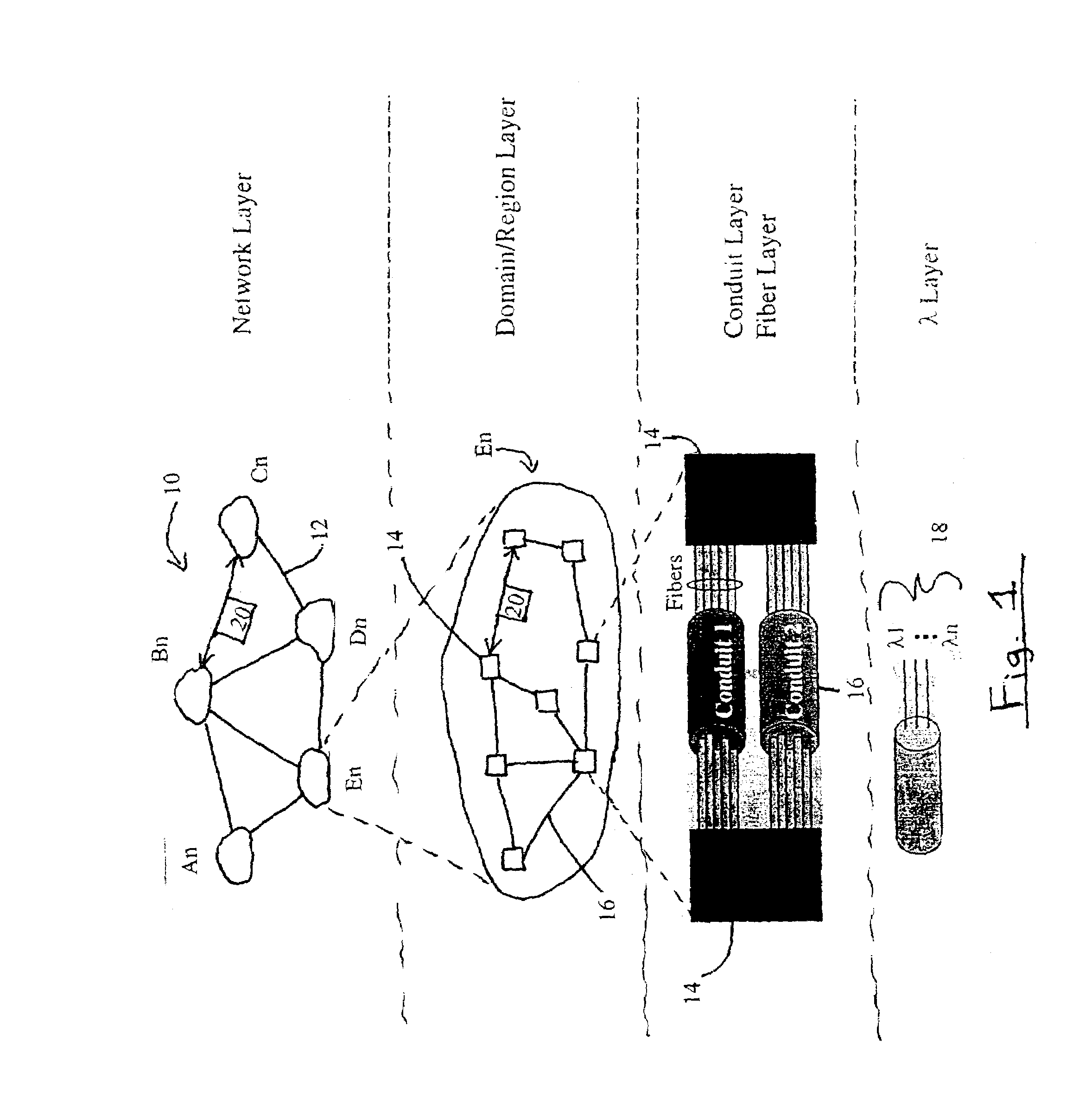
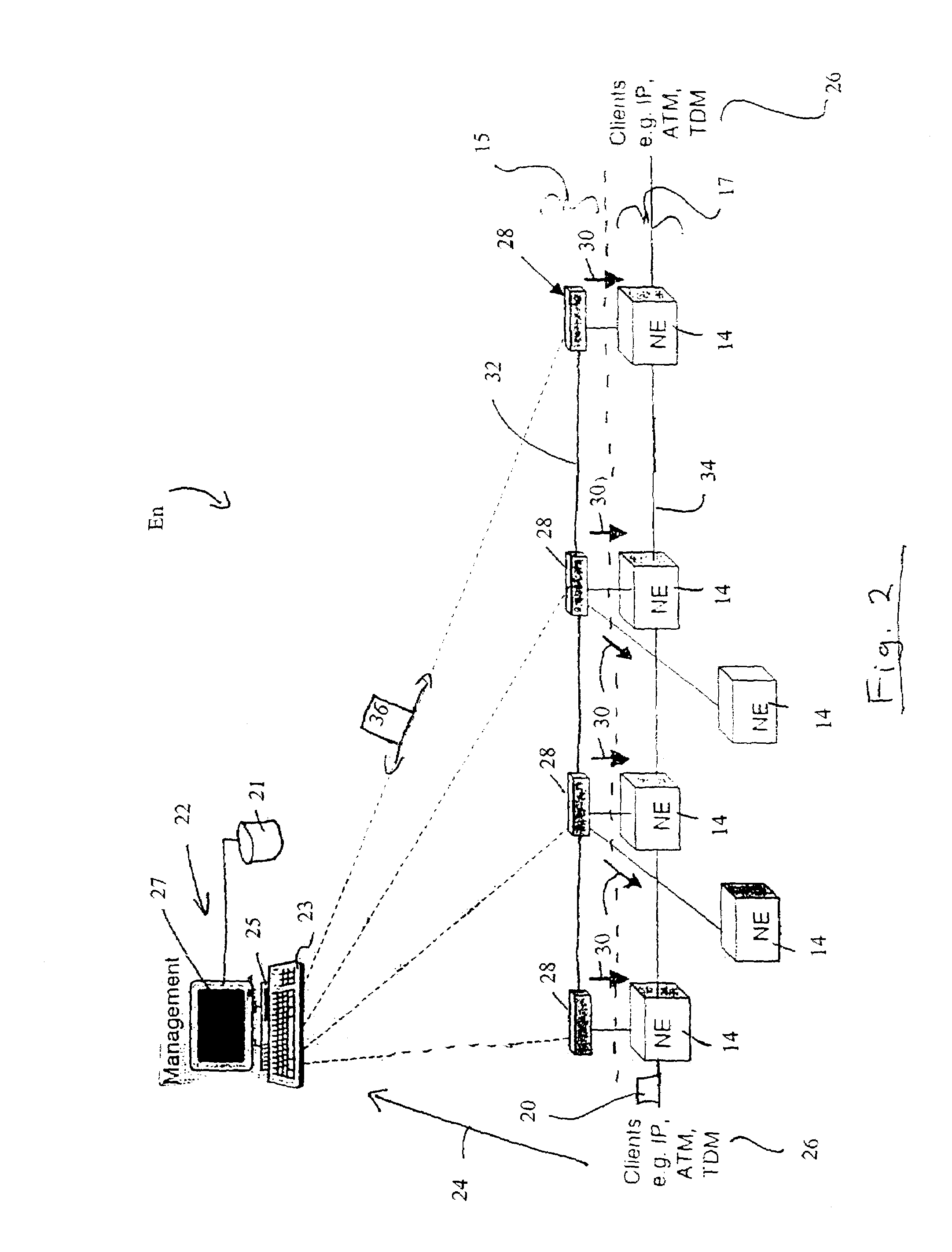
[0024]Referring to FIG. 1, a global telecommunication Network 10 contains a series of sub-networks An, Bn, Cn, Dn, En interconnected by bulk data transmission mediums 12. These mediums 12 can consist of such as but not limited to optical fiber, wireless, and copper lines which can be collectively referred to as the Backbone Network. Each sub-network An, Bn, Cn, Dn, En contains a plurality of network elements 14 interconnected by conduits 16, also referred to collectively as a control layer 15 and a line layer 17 (see FIG. 2). These conduits 16 can consist of fiber optic cables, DSL (Digital Subscriber Loop), cable, and wireless mediums, wherein each conduit 16 can be capable of providing the transmission of multiple wavelengths or signals 18 as required by the telecommunication network 10. The transmission structure of the telecommunication network 10 can be used by a variety of different carriers, such as ILECs, CLECs, ISPs, and other large enterprises to monitor and transmit a div...


PUM


Abstract

In a switching protection system, a protocol is followed by a first connection controller to help facilitate the resynchronization of the network after the failure has occurred. This protocol contains the messaging system of the ability to query and store the exact sequence of logical ports and time slots that make up the data path, as a resynchronization table coupled to the first controller. The head / ingress end of the path can receive this information during set-up and can store it both locally and in shadow locations. The system also contains the ability to distinguish between signaling and data channel failures, as signaling channel failures to do not clear cross connect data but simply leave it “ownerless”. The system also contains the ability to populate the exact sequence of logical ports and time slots accumulated in the definition of the network, as the set-up message initiated by the head controller to re-claim “ownerless” cross connections contained on respective network elements. The system also facilitates the clearing of a “ownerless” cross connection after a pre-determined period of time has lapsed.

Description

BACKGROUND OF THE INVENTION[0001]1. Field of the Invention[0002]The present invention relates to switching mechanisms for networks, and in particular to reconnection of network channels.[0003]2. Description of the Prior Art[0004]Global networks are common to all of todays telecommunication and other network systems, wherein various data, optical, and wireless devices are interconnected by a series of individual local networks. The networks generally consist of nodes and links, which describe the network topology, and associated attributes which comprise the network data. Furthermore, these networks further contain management systems that must co-ordinate the transmission of data traffic, including voice, video, and data, and other information over a variety of transmission mediums, such as wireless, copper, and fiber optic lines.[0005]Many of todays telecommunication networks are in nearly continuous use and can ill afford instances of “down” or “off-line” time in the event of netwo...

Claims


Application Information

Patent Timeline
Patent Type & Authority Patents(United States)
IPC IPC(8): H04J3/06H04J3/14H04L69/40
CPCH04J3/14H04J3/06
Inventor ASHWOOD SMITH, PETER J.BEAUBIEN, PAUL P.SKALECKI, DAREK R.
Owner RPX CLEARINGHOUSE
Why Eureka
Try Eureka