Distributed matrix switch

a technology of distributed matrix switch and switch, which is applied in the field of space switch matrix, can solve the problems of difficult implementation of an acceptable size, cost and performance, and achieve the effect of reducing size and cos

Active Publication Date: 2007-04-17
NEXTG NETWORKS INC
View PDF5 Cites 103 Cited by
  • Summary
  • Abstract
  • Description
  • Claims
  • Application Information

AI Technical Summary

Benefits of technology

[0005]According to a first aspect of the present invention, there is provided an electrical space switch matrix having m input port and n output ports on a single, multi-layer PCB. Such an arrangement provides reductions in size and cost.
[0007]In embodiments of the invention, input elements can be embodied as power splitters and output elements can be embodied as power combiners, the power splitters and plurality of power combiners being arranged so as to include crossover connection paths therebetween. As a result, crossover of connection paths is distributed between the power dividing / combining function and the switching function. Advantages of embodiments of the invention include a reduced physical size and a reduction in the number of circuit board layers (and therefore lower cost of manufacture) compared to a single large matrix, because the switch blocks can be incorporated within the crossover network of interconnection paths. This approach also leads to a reduction in the length of the interconnection paths, which gives reduced insertion loss. Furthermore, the switch block, and correspondingly the distributed matrix, can be designed with improved isolation and return loss performance for a given bandwidth compared to the single large matrix.

Problems solved by technology

However, this approach is difficult to implement with acceptable size, cost and performance.

Method used


Image

  • Distributed matrix switch
  • Distributed matrix switch
  • Distributed matrix switch

Examples


Embodiment Construction

[0020]In the following description of embodiments, reference is made to accompanying drawings which form a part hereof and in which is shown by way of illustration specific embodiments in which the invention may be practiced. It is to be understood that other embodiments may be utilized and structural changes may be made without departing from the scope of the preferred embodiments of the present invention.

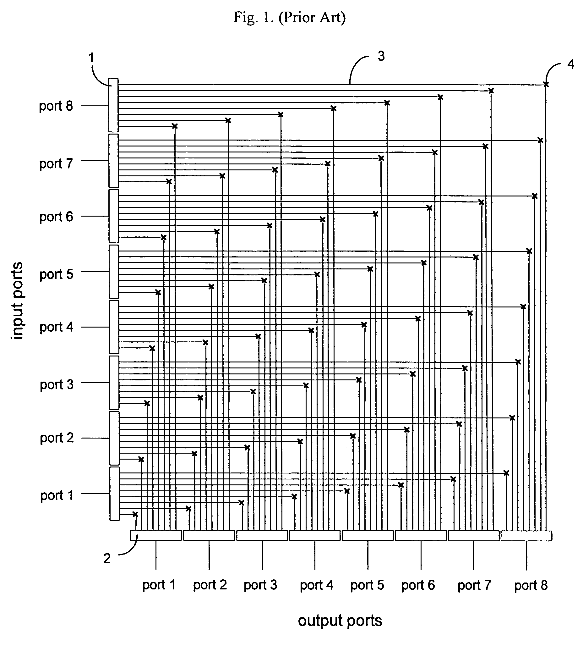
[0021]As already noted, the prior art approach to electrical space switch matrix construction is difficult to implement with acceptable size, cost and performance.

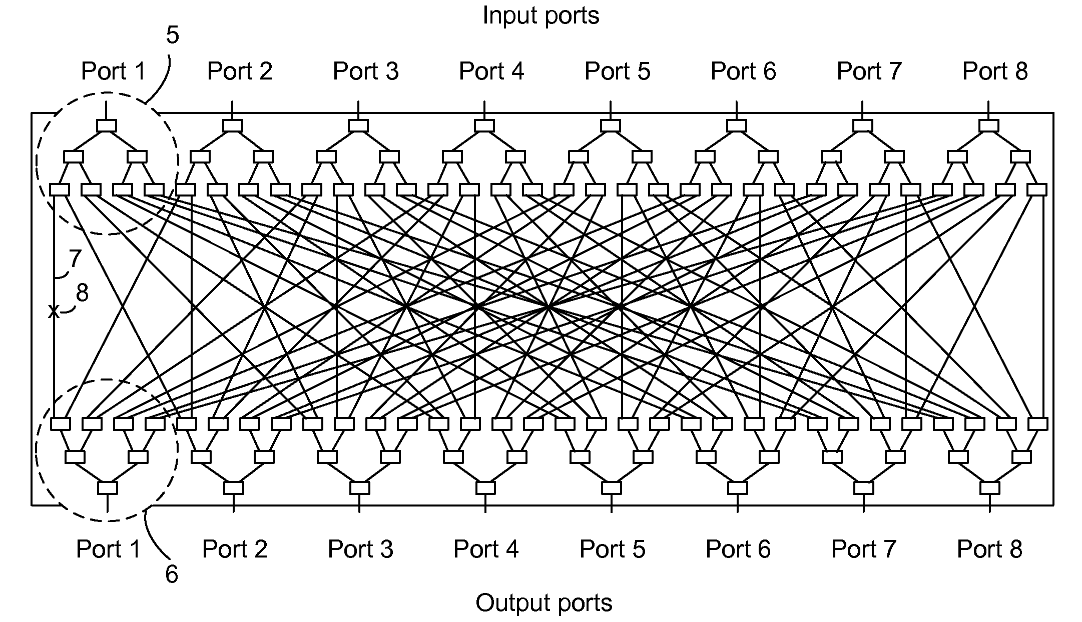
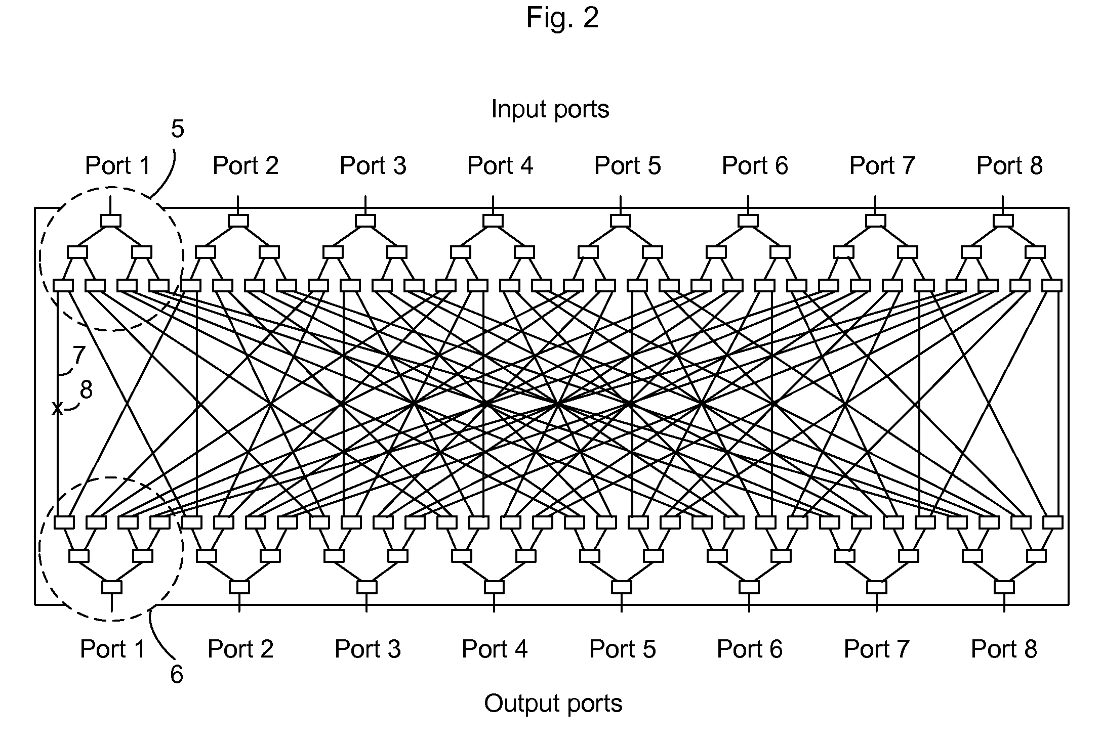
[0022]FIG. 2 shows a switch matrix implemented as a single, multi-layer PCB rather than with multiple interconnected PCBs as is the case for the switch matrix of FIG. 1. The switch matrix comprises 1:8 power dividers 5 and 8:1 power combiners 6, each of which has been deconstructed into basic 1:2 or 2:1 building blocks in this figure, and are grouped within the dashed circles only for input and output port 1 to aid clari...


PUM


Abstract

The present invention relates to an electrical space switch matrix having m input ports and n output ports, the switch matrix comprising (m.n) / (i.j) switch blocks, each having i input ports and j output ports, where i is less than m and j is less than n; and a plurality of input elements and a plurality of output elements, the plurality of input elements and plurality of output elements being arranged so as to connect the switch blocks to the input and output ports of the switch matrix. In an embodiment of the invention, the input and output elements can be power splitters and power combiners respectively and are arranged so as to include crossover connection paths therebetween, with the result that crossover of connection paths is distributed between the power dividing / combining function and the switching function.

Description

BACKGROUND OF THE INVENTION[0001]The present invention relates to a space switch matrix for electrical signals, in particular but not exclusively for switching microwave or radio frequency signals.[0002]Switching matrices for microwave or radio frequency signals are well known and have been implemented previously in a number of ways. For example U.S. Pat. No. 3,833,866 discloses an arrangement for an m×n switch matrix which comprises m (1×n) power dividers, n (1×m) power combiners and m×n switched transmission lines connecting each output arm of the dividers with each input arm of the combiners. Such an arrangement is depicted in FIG. 1 for the example case of an 8×8 switch matrix. It comprises 1:8 power dividers 1 on each of the 8 input ports, 8:1 power combiners 2 on each of the 8 output ports and 64 interconnecting transmission lines 3 each containing a terminated on-off switch 4.[0003]This type of switch matrix allows any input port to be connected to any output port. It also al...

Claims


Application Information

Patent Timeline
Patent Type & Authority Patents(United States)
IPC IPC(8): H01P1/10H01P5/12
CPCH01P1/10H04Q3/52H04Q3/68H04Q2213/1302H04Q2213/1304
Inventor SCHULTZ, JR., JOHN C. F.CRAWFORD, LAWRENCE GRIFFIN
Owner NEXTG NETWORKS INC
Why Eureka
Try Eureka