Optical disk device controlling a revolution of a recordable optical disk according to a displacement between a phase of a sector synchronizing signal generated from a data-writing reference clock signal and a phase of a synchronizing signal obtained from address
a technology of optical disk and revolution, which is applied in the field of optical disk devices, can solve the problems of data recording failure, data-writing reference clock signal overrun, and data recording failur
- Summary
- Abstract
- Description
- Claims
- Application Information
AI Technical Summary
Benefits of technology
Problems solved by technology
Method used
Image

Examples
embodiment 1
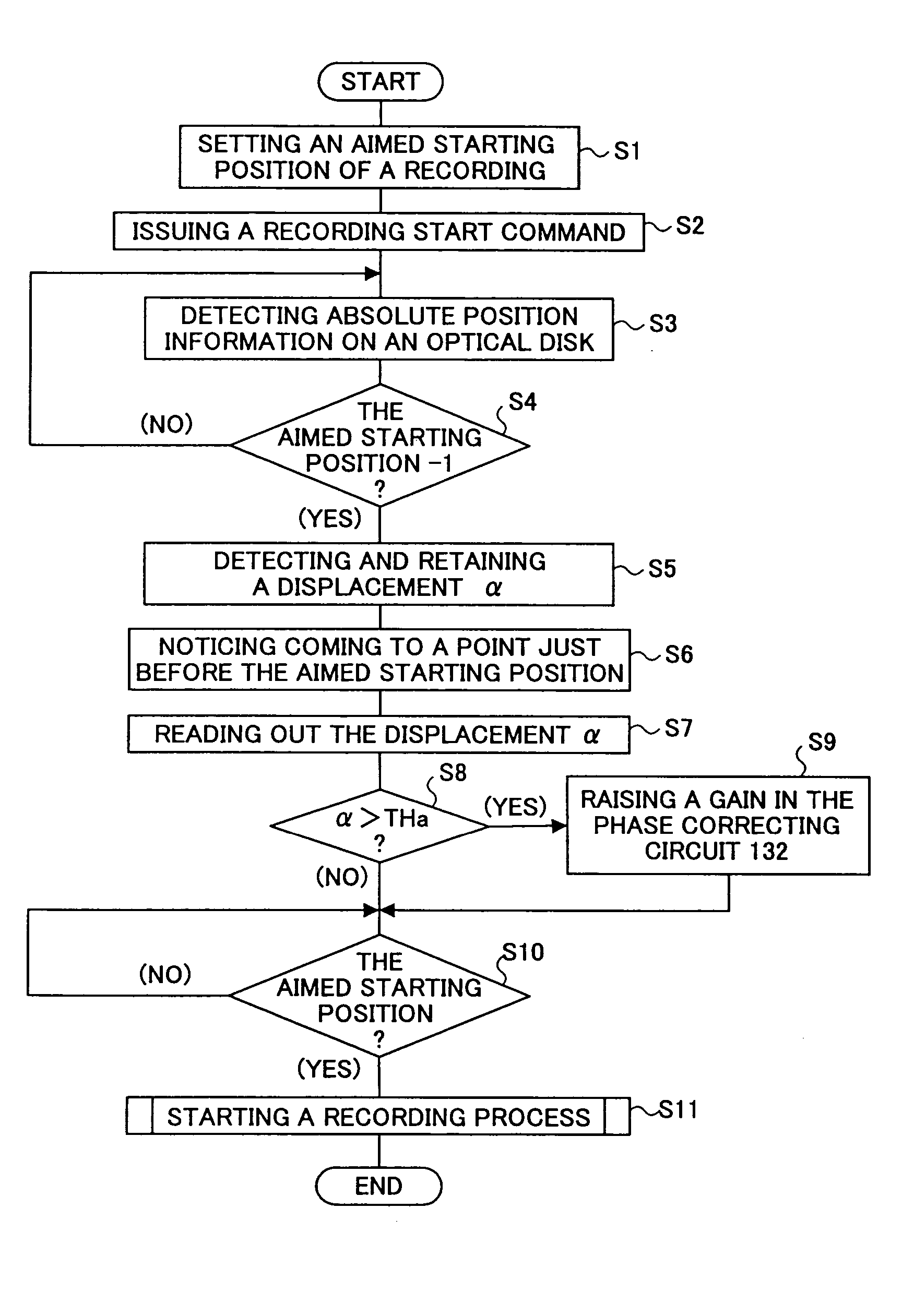
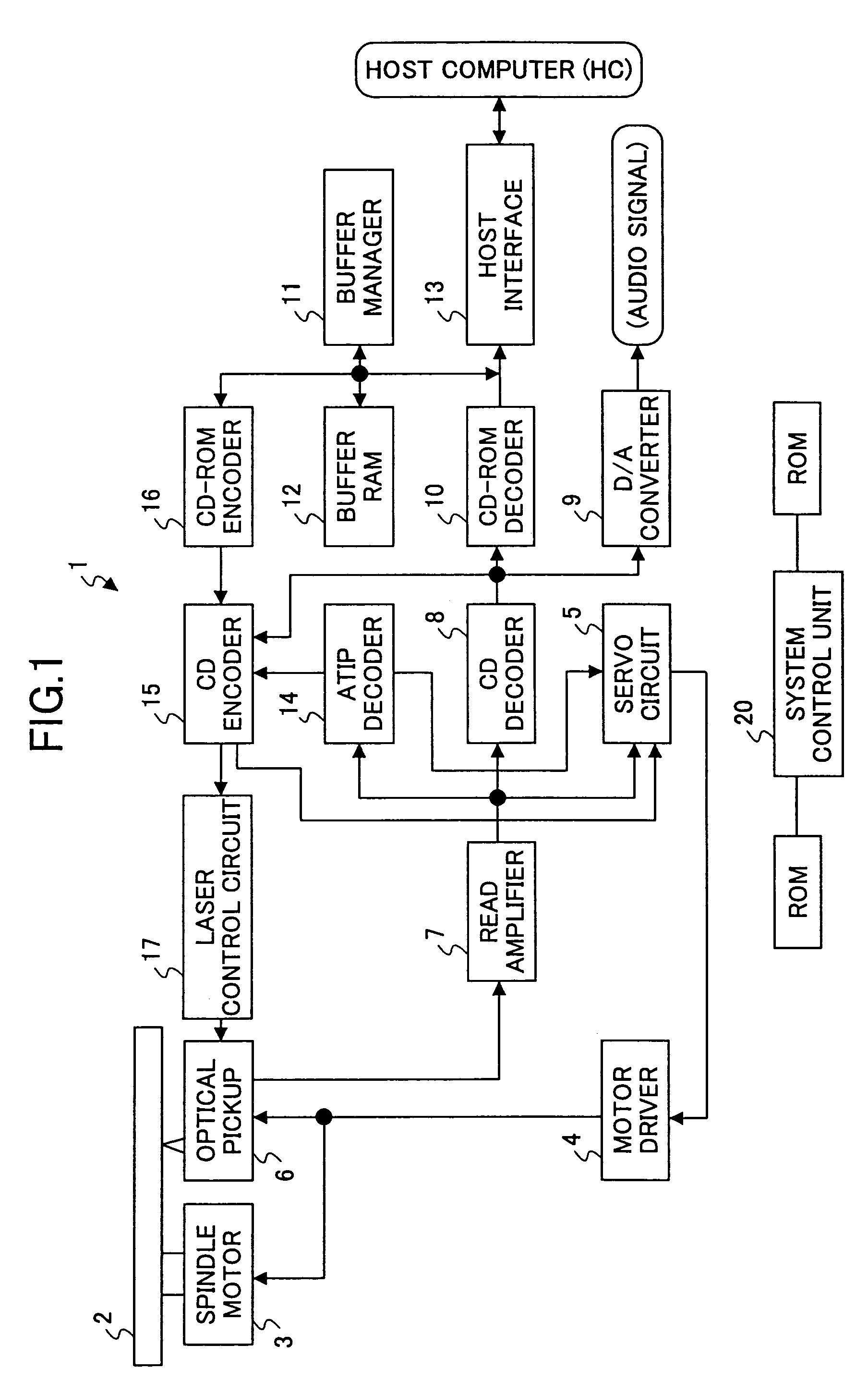
[0064]FIG. 1 is a block diagram outlining an example of a structure of an optical disk device according to a first embodiment of the present invention, taking a CD-R as an example.
[0065]In an optical disk device 1 shown in FIG. 1, an optical disk 2 is revolved by a spindle motor 3. This spindle motor 3 is controlled by a motor driver 4 and a servo circuit (a data-writing control unit) 5 so that a linear velocity becomes constant. This linear velocity can be changed step by step.
[0066]An optical pickup 6 reading and writing data from / to the optical disk 2 includes a semiconductor laser, an optical system, a focus actuator, a track actuator, a light-receiving element, and a position sensor (not shown in the figure) incorporated therein. The optical pickup 6 projects a laser beam upon the optical disk 2 so as to read and write data therefrom / thereto. Additionally, the optical pickup 6 can be moved toward a sledge by a seek motor (not shown in the figure). The above-mentioned focus actu...
embodiment 2
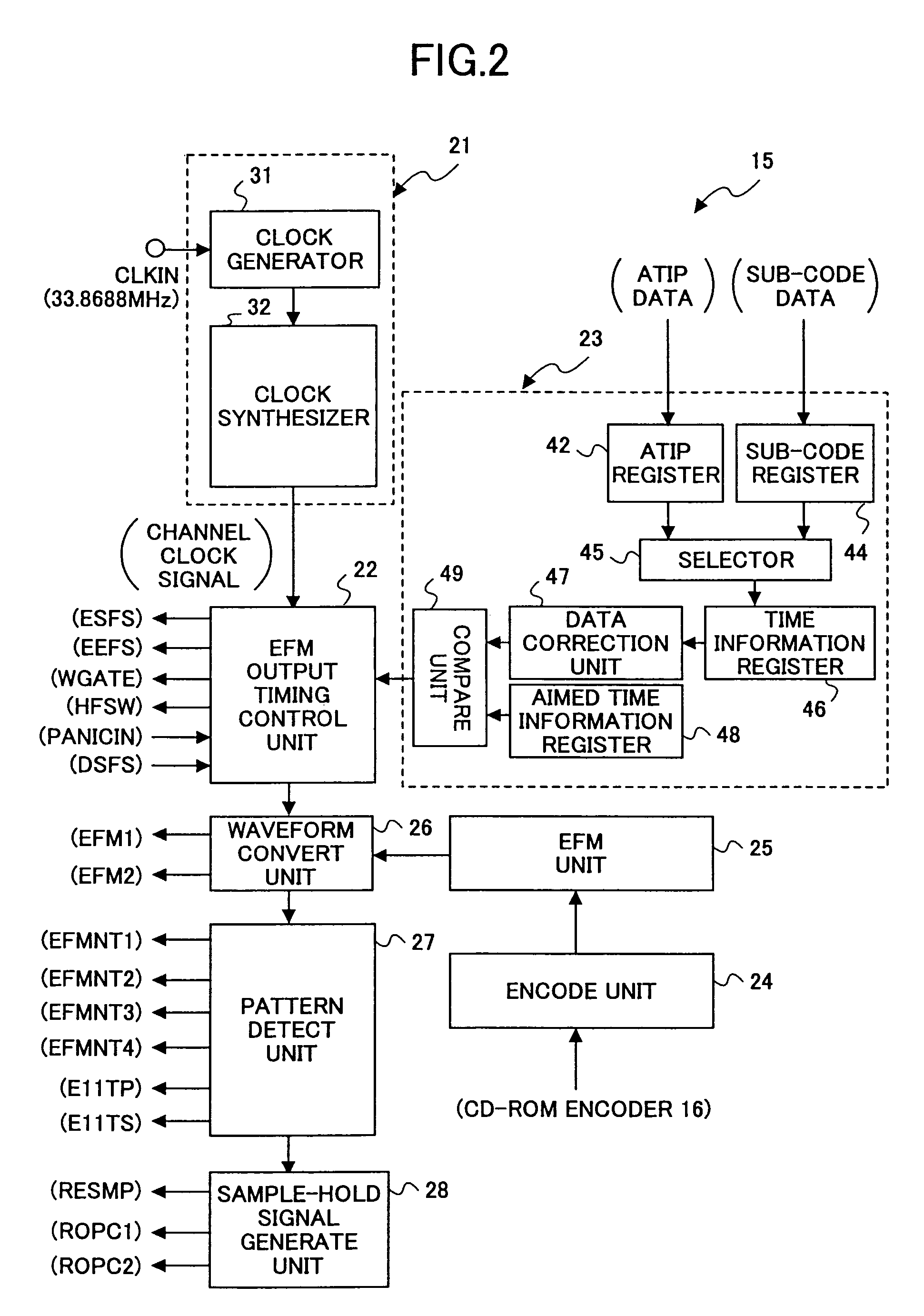
[0126]In the above-described first embodiment, the gain in the phase correcting circuit 132 is switched according to whether or not the displacement α surpasses the threshold value THa. However, the gain in the phase correcting circuit 132 may be switched according to whether or not the displacement α surpasses a displacement detected last time. A second embodiment of the present embodiment achieves this arrangement.
[0127]Based on the optical disk device 1 according to the above-described first embodiment, an optical disk device 1a according to the present second embodiment further comprises a history-information register (not shown in the figure) in the EFM output timing control unit 22 of the CD encoder 15, the history-information register retaining history information of the displacement α, for example, the displacement α detected last time. Accordingly, in the optical disk device 1a, the EFM output timing control unit 22 is an EFM output timing control unit 22a, and the CD encod...
embodiment 3
[0134]The gain once switched may be switched back to the previous gain after a predetermined period has elapsed. A third embodiment of the present embodiment achieves this arrangement.
[0135]Based on the optical disk device 1 according to the above-described first embodiment, an optical disk device 1b according to the present third embodiment further comprises a present-position information register (not shown in the figure) in the EFM output timing control unit 22 of the CD encoder 15. In this structure, present-position information is supplied from the data correction unit 47 via the compare unit 49 to the EFM output timing control unit 22, and is stored in the above-mentioned present-position information register. The EFM output timing control unit 22 supplies the system control unit 20 with a predetermined interrupt signal corresponding to the pulse of the ESFS signal. Accordingly, in the optical disk device 1b, the EFM output timing control unit 22 is an EFM output timing contro...
PUM
| Property | Measurement | Unit |
|---|---|---|
| time | aaaaa | aaaaa |
| frequency | aaaaa | aaaaa |
| phase | aaaaa | aaaaa |
Abstract
Description
Claims
Application Information
 - R&D Engineer
- R&D Manager
- IP Professional
- Industry Leading Data Capabilities
- Powerful AI technology
- Patent DNA Extraction
Browse by: Latest US Patents, China's latest patents, Technical Efficacy Thesaurus, Application Domain, Technology Topic.
© 2024 PatSnap. All rights reserved.Legal|Privacy policy|Modern Slavery Act Transparency Statement|Sitemap