Optical disk device controlling a revolution of a recordable optical disk according to a displacement between a phase of a sector synchronizing signal generated from a data-writing reference clock signal and a phase of a synchronizing signal obtained from address information

Inactive Publication Date: 2004-03-25
RICOH KK
View PDF2 Cites 9 Cited by
  • Summary
  • Abstract
  • Description
  • Claims
  • Application Information

AI Technical Summary

Benefits of technology

[0016] A more specific object of the present invention is to provide an optical disk device which can provide a stable and optimal recording control by, upon resuming a data-recording to an optical disk device, detecting a displacement between the phase of an EFM frame sync signal obtained by reproducing data recorded last time and the phase of a sector synchronizing signal generated by a data-writing reference clock signal generating unit so as to be used to obtain a data-writing timing for recording data to the optical disk device.

Problems solved by technology

When the data-recording to the optical disk is suspended, the data-recording fails because the data cannot be written additionally.
As the recording speed to the optical disk becomes higher, the buffer-underrun is more likely to occur, and the resulting failure of the data-recording poses a serious problem for a user, because a CD-R is a write once type, in which a failure of a data-recording means a loss of an optical disk and a loss of the data already written or to be written.
However, increasing the capacity of the buffer RAM is not a good measure, because increasing the capacity of the buffer RAM leads to raising a cost of the optical disk device as a whole.
Additionally, the buffer RAM cannot deal with all cases related to the differences in a throughput of host computers.
However, this method involves a complicated structure and control, because the data-recording speed needs to be switched during a data-recording to the optical disk.
However, when performing the above-mentioned control of detecting an ending position of the previous recording and accurately resuming the data-recording from the ending position, under the situation where a data-recording operation is frequently stopped and resumed, a displacement may occur between absolute time information (ATIP absolute time information) and a position of recorded data, and when the displacement actually occurs, the displacement is accumulated.
In both cases, there is a possibility that data may not be reproduced accurately.
The seriousness of this problem depends on the number of times a data-recording operation is temporarily stopped and resumed which affects the accumulation of displacement, and also depends on a length of a period from a resumption of the data-recording operation until a stop thereof which affects the time to be taken for a motor revolution control to transit from an unstable state to a stable state.

Method used


Image

  • Optical disk device controlling a revolution of a recordable optical disk according to a displacement between a phase of a sector synchronizing signal generated from a data-writing reference clock signal and a phase of a synchronizing signal obtained from address information
  • Optical disk device controlling a revolution of a recordable optical disk according to a displacement between a phase of a sector synchronizing signal generated from a data-writing reference clock signal and a phase of a synchronizing signal obtained from address information
  • Optical disk device controlling a revolution of a recordable optical disk according to a displacement between a phase of a sector synchronizing signal generated from a data-writing reference clock signal and a phase of a synchronizing signal obtained from address information

Examples


first embodiment

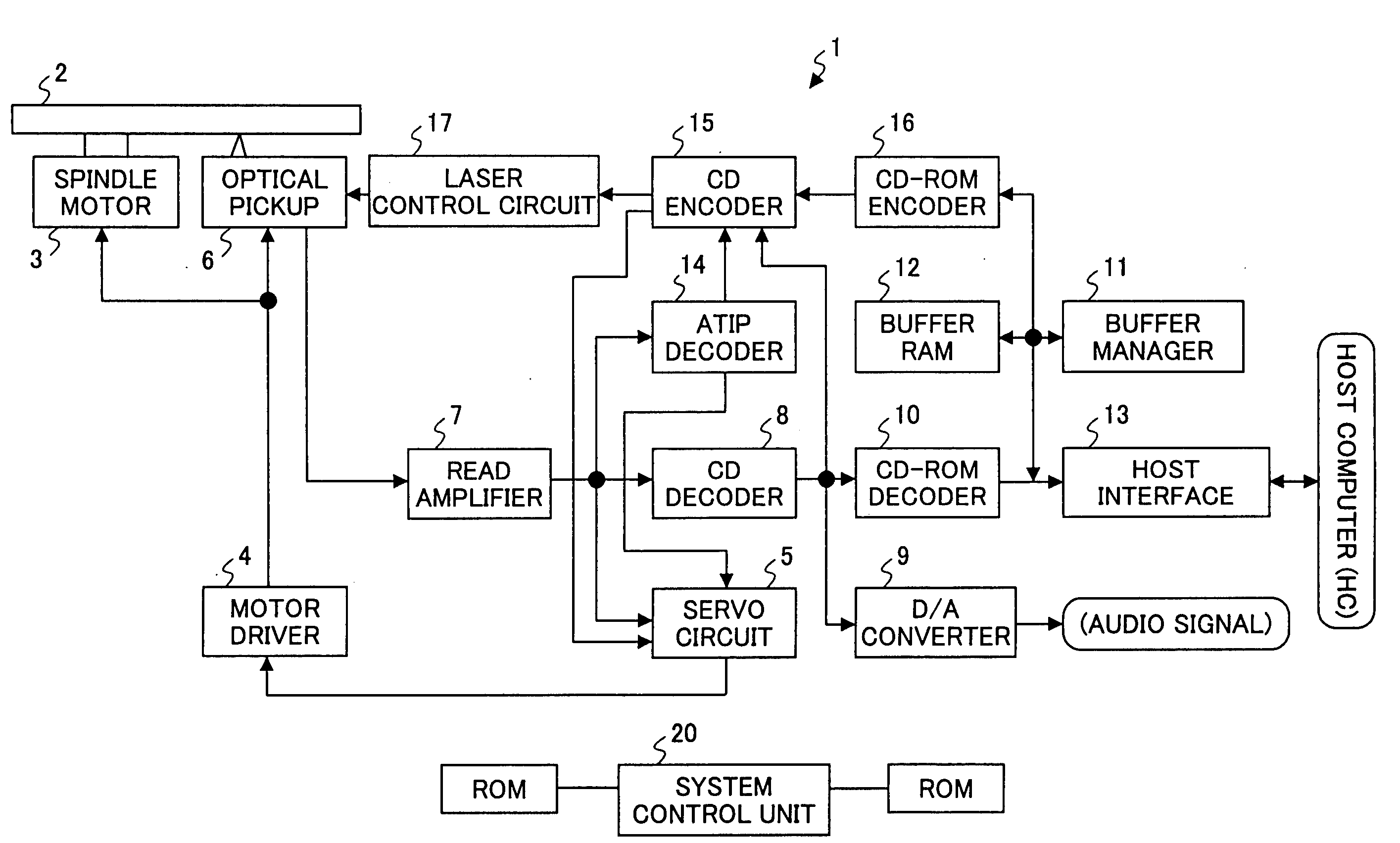
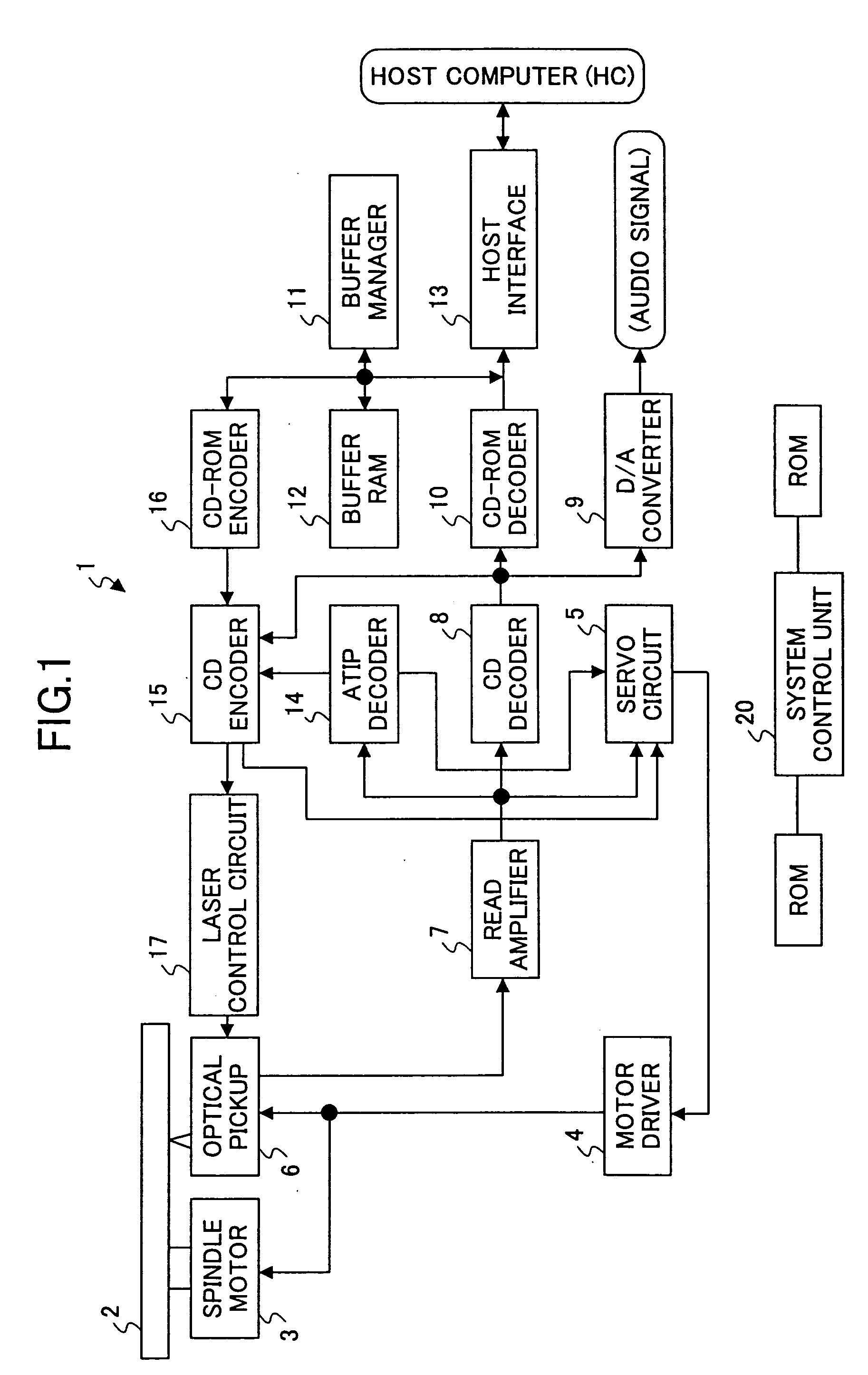
[0063] FIG. 1 is a block diagram outlining an example of a structure of an optical disk device according to the present invention, taking a CD-R as an example.

[0064] In an optical disk device 1 shown in FIG. 1, an optical disk 2 is revolved by a spindle motor 3. This spindle motor 3 is controlled by a motor driver 4 and a servo circuit (a data-writing control unit) 5 so that a linear velocity becomes constant. This linear velocity can be changed step by step.

[0065] An optical pickup 6 reading and writing data from / to the optical disk 2 includes a semiconductor laser, an optical system, a focus actuator, a track actuator, a light-receiving element, and a position sensor (not shown in the figure) incorporated therein. The optical pickup 6 projects a laser beam upon the optical disk 2 so as to read and write data therefrom / thereto. Additionally, the optical pickup 6 can be moved toward a sledge by a seek motor (not shown in the figure). The above-mentioned focus actuator, the, track ac...

embodiment 2

[0125] In the above-described first embodiment, the gain in the phase correcting circuit 132 is switched according to whether or not the displacement .alpha. surpasses the threshold value THa. However, the gain in the phase correcting circuit 132 may be switched according to whether or not the displacement .alpha. surpasses a displacement detected last time. A second embodiment of the present embodiment achieves this arrangement.

[0126] Based on the optical disk device 1 according to the above-described first embodiment, an optical disk device 1a according to the present second embodiment further comprises a history-information register (not shown in the figure) in the EFM output timing control unit 22 of the CD encoder 15, the history-information register retaining history information of the displacement .alpha., for example, the displacement .alpha. detected last time. Accordingly, in the optical disk device 1a, the EFM output timing control unit 22 is an EFM output timing control ...

embodiment 3

[0133] The gain once switched may be switched back to the previous gain after a predetermined period has elapsed. A third embodiment of the present embodiment achieves this arrangement.

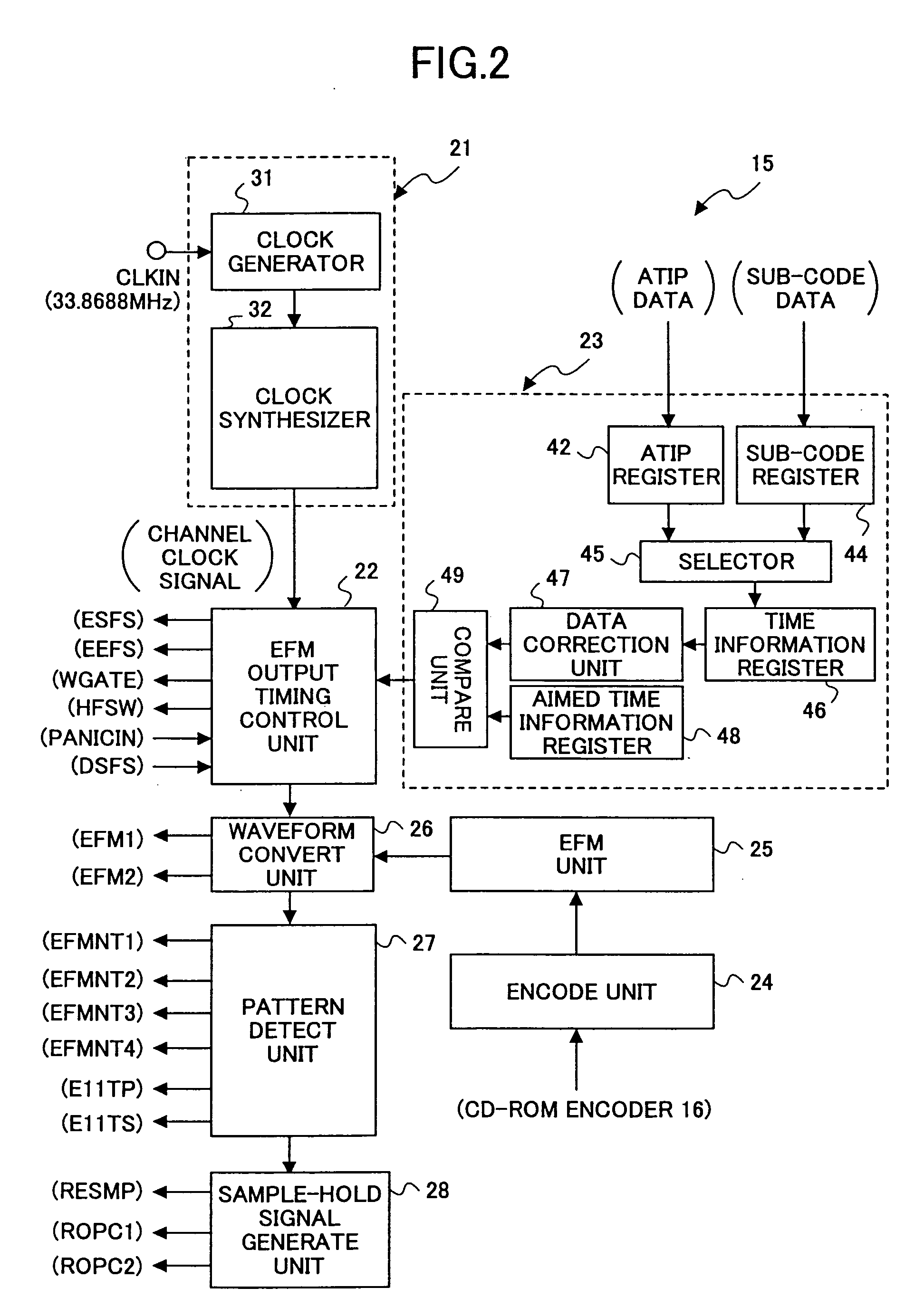
[0134] Based on the optical disk device 1 according to the above-described first embodiment, an optical disk device 1b according to the present third embodiment further comprises a present-position information register (not shown in the figure) in the EFM output timing control unit 22 of the CD encoder 15. In this structure, present-position information is supplied from the data correction unit 47 via the compare unit 49 to the EFM output timing control unit 22, and is stored in the above-mentioned present-position information register. The EFM output timing control unit 22 supplies the system control unit 20 with a predetermined interrupt signal corresponding to the pulse of the ESFS signal. Accordingly, in the optical disk device 1b, the EFM output timing control unit 22 is an EFM output timing cont...


PUM


Abstract

An optical disk device that records and reproduces information on / from a recordable optical disk is provided. The optical disk device comprises a reference clock signal generating unit generating a data-writing reference clock signal used to obtain a data-writing timing upon recording data to the optical disk, a synchronizing signal generating unit generating a predetermined sector synchronizing signal from the data-writing reference clock signal, a data demodulating unit reading address information indicating a position on the optical disk from data recorded on the optical disk so as to demodulate the address information into a predetermined synchronizing signal, a displacement detecting unit detecting a displacement between a phase of the sector synchronizing signal and a phase of the synchronizing signal; and a data-writing control unit controlling a data-writing upon performing an additional recording to the optical disk by controlling a revolution of the optical disk dynamically according to the displacement.

Description

[0001] 1. Field of the Invention[0002] The present invention generally relates to an optical disk device which records and reproduces information to / from a writable optical disk, and more particularly, to a technology for preventing the occurrence of a buffer-underrun during a data-recording.[0003] 2. Description of the Related Art[0004] A writable optical disk has a relatively large unit into which to write data due to characteristics of a recording format. Many of conventional optical disk devices do not cause a data-recording to an optical disk to pause. Therefore, unless data is transmitted from a host computer to the optical disk device at a higher transfer rate than a recording speed of the optical disk device to the optical disk, the data-recording comes to be suspended. When the data-recording to the optical disk is suspended, the data-recording fails because the data cannot be written additionally.[0005] This is called a buffer-underrun. As the recording speed to the optica...

Claims


Application Information

Patent Timeline
IPC IPC(8): G11B20/14G11B7/0037G11B7/0045G11B19/247G11B19/28
CPCG11B19/247
Inventor BANNO, MASAHIKO
Owner RICOH KK
Why Eureka
Try Eureka