Refrigerant system with common economizer and liquid-suction heat exchanger

a technology of liquid-suction heat exchanger and refrigerant system, which is applied in the direction of refrigeration components, mechanical equipment, lighting and heating equipment, etc., can solve the problems of high cost and cumbersome provision of both options

Inactive Publication Date: 2006-10-03
CARRIER CORP
View PDF3 Cites 83 Cited by
  • Summary
  • Abstract
  • Description
  • Claims
  • Application Information

AI Technical Summary

Problems solved by technology

This scheme provides additional cooling capacity when the refrigerant reaches the evaporator, but at the expense of having higher temperature and lower density refrigerant reaching the compressor.
Providing both options has been expensive and somewhat cumbersome as two separate heat exchangers were required.

Method used


Image

  • Refrigerant system with common economizer and liquid-suction heat exchanger
  • Refrigerant system with common economizer and liquid-suction heat exchanger
  • Refrigerant system with common economizer and liquid-suction heat exchanger

Examples


embodiment 60

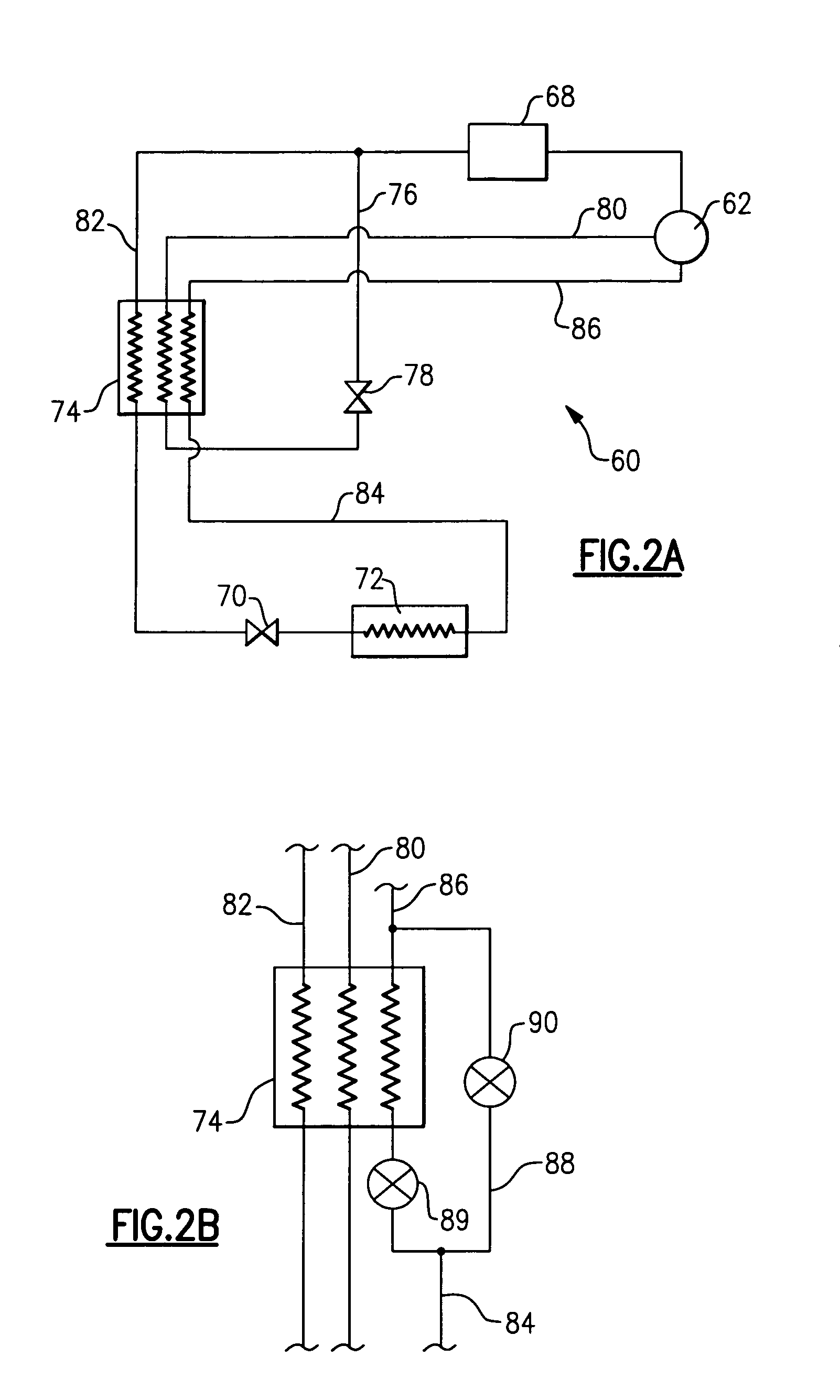
[0025]FIG. 2A shows another embodiment 60 with the economized compressor 62. Refrigerant downstream of the compressor 62 passes through a condenser 68, a main expansion device 70, and an evaporator 72. A common heat exchanger 74 receives refrigerant from an economizer circuit tap line 76 through an economizer expansion device 78. The tapped refrigerant would flow through an economizer circuit return line 80 back to the economizer port of the compressor 62 at some intermediate pressure. The main liquid refrigerant line 82 downstream of the condenser also passes through the common heat exchanger 74. A line 84 downstream of the evaporator 72 passes through the common heat exchanger 74 as well, and then back to a suction line 86 that returns refrigerant to the suction port of the compressor 62. This schematic selectively provides an economizer function by opening or closing the economizer expansion device 78. In case the economizer expansion device 78 is not equipped with a shutoff capa...

embodiment 100

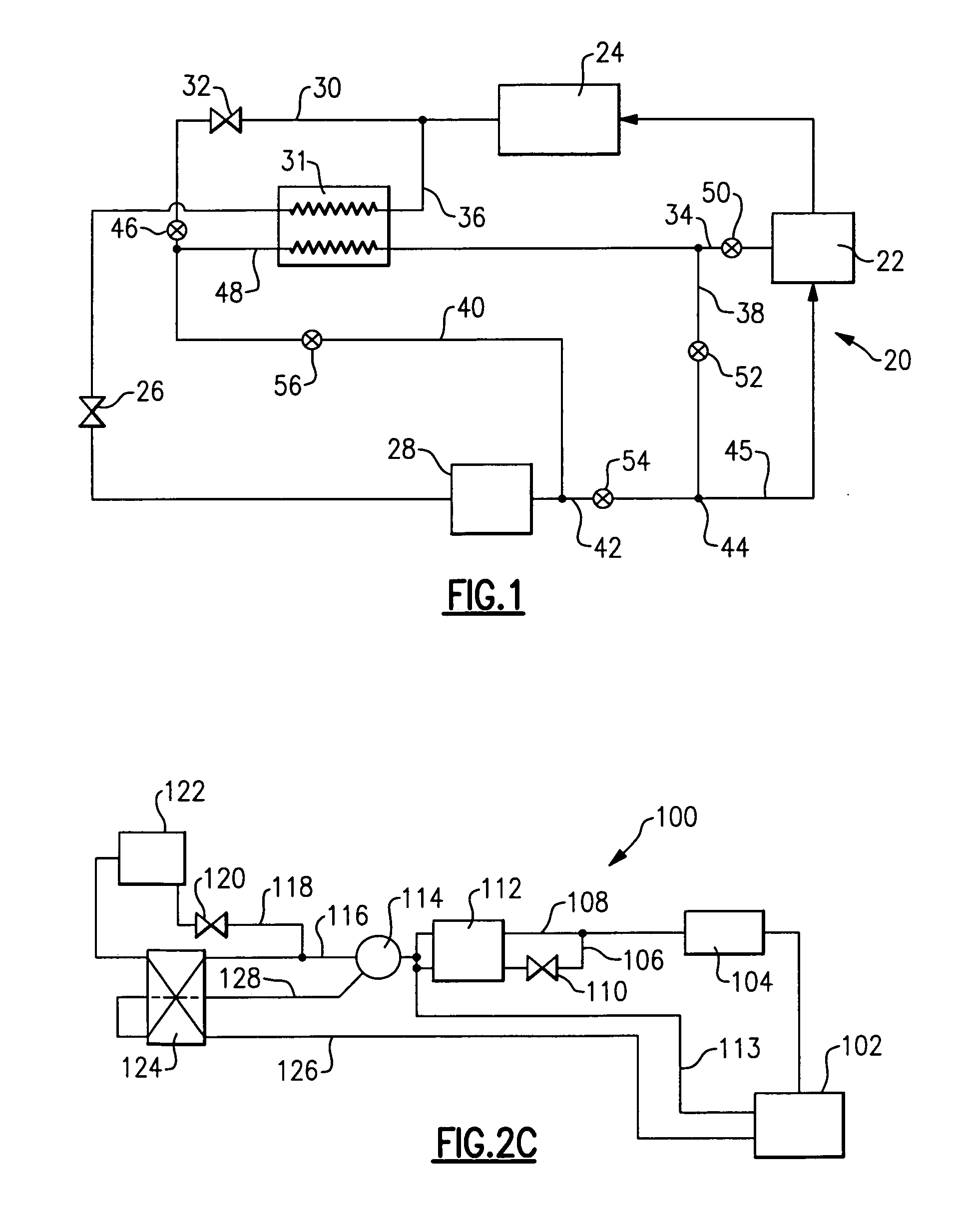
[0027]Another embodiment 100 shown in FIG. 2C is a variation of the configuration presented in FIG. 2B. In this embodiment, an economizer function and a liquid-suction heat exchanger function are provided by separate units, 112 and 124 respectively, while a three-way valve 114 selectively routes the refrigerant through or around the liquid-suction heat exchanger 124.

[0028]An economized compressor 102 delivers refrigerant to a downstream condenser 104. A tap 106 from a main liquid refrigerant line 108 passes through an economizer expansion device 110, which is also utilized as a shut-off valve in this schematic. The refrigerant from both the tap 106 and main liquid refrigerant line 108 flows through the economizer heat exchanger 112. In fact, while the two are shown flowing in the same direction, in practice, it would be preferable if they were in a counter-flow relationship. If no economizer function is desired, then valve 110 is shut. The three-way valve 114 receives the refrigeran...


PUM


Abstract

A refrigerant system is provided where the functions of an economizer heat exchanger and liquid-suction heat exchanger are combined. The two configurations are disclosed with a single common heat exchanger construction. In a first configuration, a series of valves selectively routes only one of two possible refrigerant flows through a common heat exchanger such that a control can selectively activate either an economizer heat exchanger circuit or a liquid-suction heat exchanger function. In a second configuration, both refrigerant flows are passed to the common heat exchanger through separate fluid lines and are selectively activated by the control. Variations of the second configuration are also disclosed.

Description

BACKGROUND OF THE INVENTION[0001]This invention relates to a refrigerant system that incorporates an economizer heat exchanger and liquid-suction heat exchanger within a single common heat exchanger construction.[0002]Refrigerant systems are utilized in applications to change the temperature and humidity or otherwise condition the environment. In a standard refrigerant system, a compressor delivers a compressed refrigerant to an outdoor heat exchanger, known as a condenser. From the condenser, the refrigerant passes through an expansion device, and then to an indoor heat exchanger, known as an evaporator. In the evaporator, moisture may be removed from the air, and the temperature of air blown over the evaporator coil is lowered. From the evaporator, the refrigerant returns to the compressor. Of course, basic refrigerant systems are utilized in combination with many configuration variations and optional features. However, the above provides a brief understanding of the fundamental c...

Claims


Application Information

Patent Timeline
Patent Type & Authority Patents(United States)
IPC IPC(8): F25B41/00F25B49/00
CPCF25B40/00F25B41/04F25B41/043F25B1/10F25B2400/04F25B2400/13F25B2600/0261F25B2600/2509F25B41/22F25B41/20F25B41/24
Inventor LIFSON, ALEXANDERTARAS, MICHAEL F.FRASER, JR., HOWARD H.LEWIS, RUSSELL G.STUMPF, ANDRE
Owner CARRIER CORP
Why Eureka
Try Eureka