Control system for watercraft propulsion units

a control system and watercraft technology, applied in marine propulsion, vessel construction, instruments, etc., can solve the problems of inefficient use, inconvenient operation, and the inability of the operator to operate six shift and throttle levers, so as to reduce the time the outboard motor operates in neutral, prevent awkward feelings, and reduce the effect of the outboard motor

Active Publication Date: 2006-10-17
YAMAHA MARINE KK
View PDF7 Cites 30 Cited by
  • Summary
  • Abstract
  • Description
  • Claims
  • Application Information

AI Technical Summary

Benefits of technology

[0011]An aspect of at least one of the embodiments disclosed herein includes the realization that a middle outboard motor can be controlled so as to operate at an averaged speed or to generate an averaged thrust of the outer outboard motors. As such, the outboard motor is utilized efficiently, reducing the time it operates in neutral, and can prevent awkward feelings that result from prior art control systems.

Problems solved by technology

However, it can be a burden for the operator to operate six shift and throttle levers in addition to operating a steering device.
Thus, the central outboard motor either interferes with the desired maneuver, or it is not used efficiently.
For example, if either of the left and the right outboard motor is driven for advancing and the other for reversing to effect turning of the hull, the central outboard motor is set in neutral unconditionally, so that the central outboard motor cannot be used effectively in response to the conditions, for example, of turning round in advancing or reversing.
Also, if both of the left and right outboard motors have thrusts in the same direction but different in magnitude, since the central outboard motor is driven to be suited to one of the left and right outboard motors, an awkward feeling may be given or unnecessary thrust may be generated.

Method used


Image

  • Control system for watercraft propulsion units
  • Control system for watercraft propulsion units
  • Control system for watercraft propulsion units

Examples


first embodiment

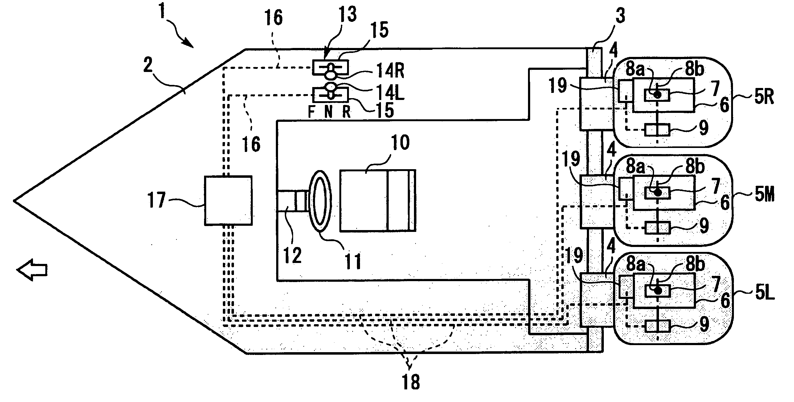
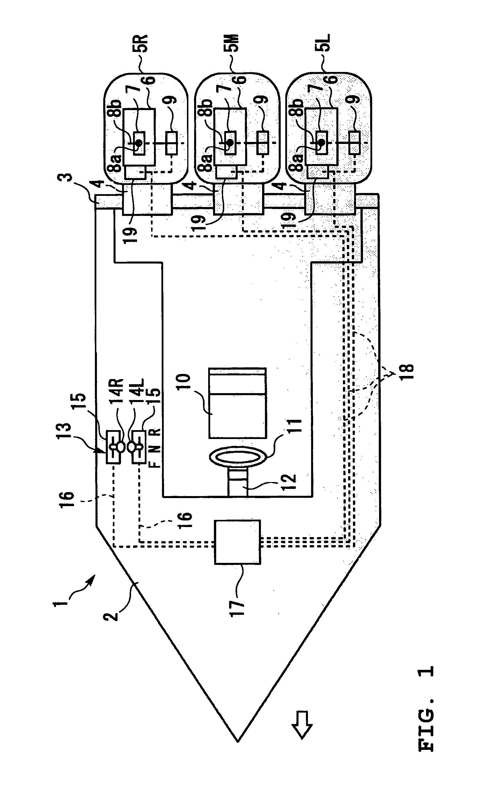
[0051]FIG. 6 shows a watercraft provided with four propulsion units controlled by the controller. Like parts are designated by the like reference numerals as in the

[0052]As shown in FIG. 6, in this case a watercraft 20 has four outboard motors mounted in parallel on a transom plate 3, and these outboard motors are referred to as a left unit 5L, a left-middle unit 5LM, a right-middle unit 5RM, and a right unit 5R in due order from the left. A lever 14L shown in FIG. 5 by a solid line is the left remote control lever for the shift change and opening adjustment (thrust control) of the throttle valve 8a of the left unit 5L, and a lever 14R, the right remote control lever for the shift change and opening adjustment (thrust control) of the throttle valve 8a of the right unit 5R. An imaginary lever 14 LM shown in FIG. 5 by a dotted line governs the operation of the left-middle unit 5LM, and imaginary lever 14 RM governs the operation of the right-middle unit 5RM.

[0053]In this variation, th...

second embodiment

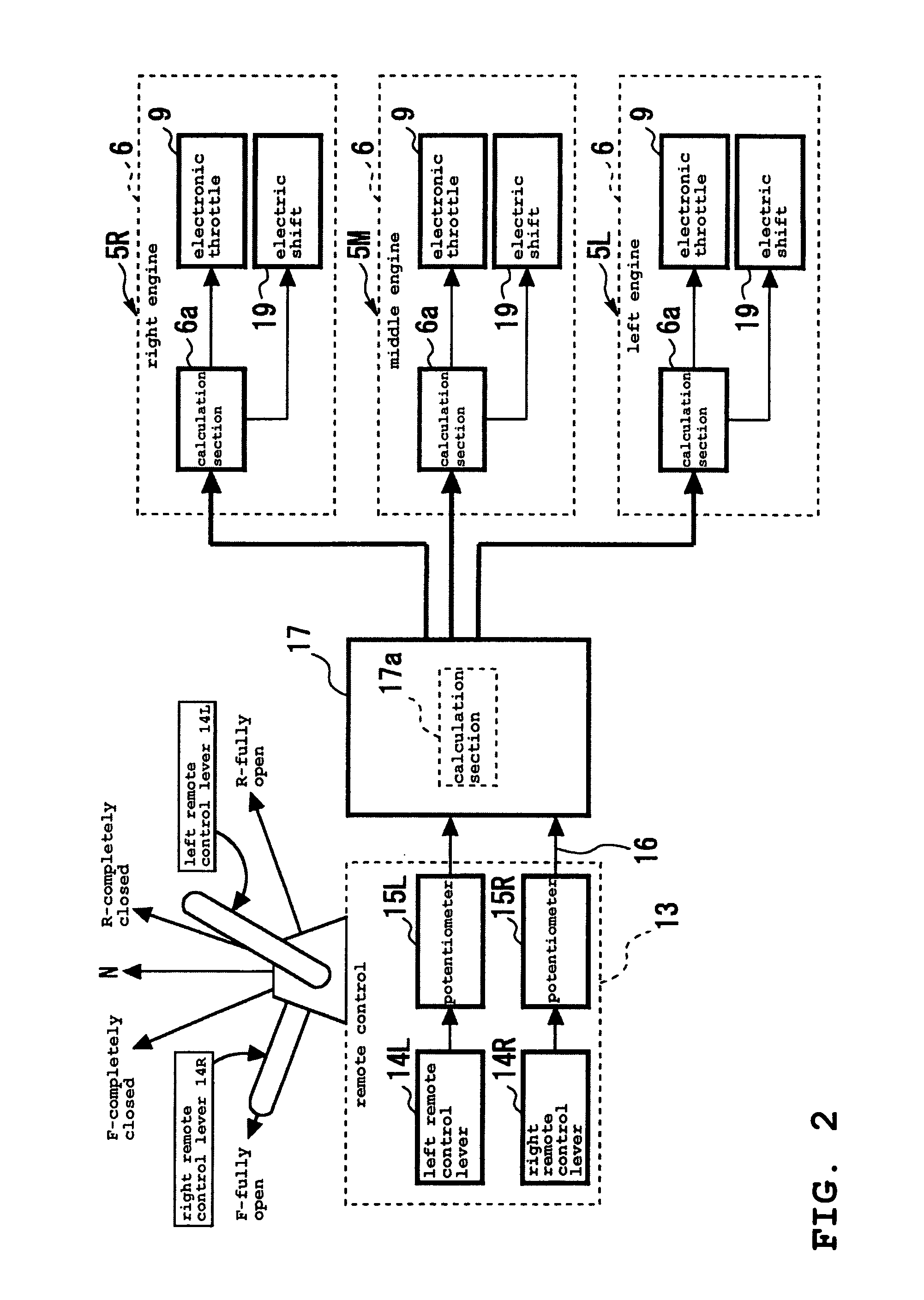
[0063]FIG. 9 and FIG. 10 illustrate an example of a thrust setting technique for outboard motors in a watercraft of four-unit type. FIG. 9 shows the controller 13, and FIG. 10 shows the relation between lever position of the remote control lever of the controller 13 and engine thrust corresponding to the lever position. The watercraft provided with four outboard motors drive-controlled by the controller 13 is the same as that of FIG. 6. Like parts are designated by like reference numerals as in the

[0064]In this variation, as in the embodiments described above with reference to FIGS. 7 and 8, first the control circuit 17 (FIG. 2) reads lever positions of the left and right remote control levers 14L, 14R, calculates for the engine of the left unit 5L, a thrust P1 corresponding to the lever position of the left remote control lever 14L in the calculation section 17a and outputs a drive signal corresponding to the thrust P1. On the other hand, the control circuit calculates for the engi...


PUM


Abstract

A watercraft control system is provided in which shift and thrust of outboard motors can be controlled through adjacent two operating levers in the watercraft having three or more outboard motors mounted in parallel on a transom plate. The control system can be provided with a control circuit for detecting lever positions of the operating levers and controlling the left unit according to the lever position of the left operating lever and the right unit according to the lever position of the right operating lever. The control circuit can be provided with a calculation circuit for calculating an imaginary lever position of the middle unit from the lever positions detected.

Description

PRIORITY INFORMATION[0001]This application is based on and claims priority under 35 U.S.C. §119 to Japanese Patent Application No. 2004-214417, filed on Jul. 22, 2004, the entire contents of which is hereby expressly incorporated by reference herein.BACKGROUND OF THE INVENTIONS[0002]1. Field of the Inventions[0003]The present inventions relate to a control system for watercraft propulsion units and particularly to a watercraft control system having three or more watercraft propulsion units disposed in parallel in a hull.[0004]2. Description of the Related Art[0005]Some watercraft can have three outboard motors mounted on a transom thereof, in a side-by-side arrangement. Conventionally, such watercraft incorporate three sets of shift and throttle levers, each of which corresponds to a respective outboard motor. However, it can be a burden for the operator to operate six shift and throttle levers in addition to operating a steering device.[0006]Recently, an improved control device for...

Claims


Application Information

Patent Timeline
Patent Type & Authority Patents(United States)
IPC IPC(8): B63H21/22
CPCB63H20/00B63H21/213B63H2020/003
Inventor OKUYAMA, TAKASHI
Owner YAMAHA MARINE KK
Why Eureka
Try Eureka