Power transmission mechanism

a transmission mechanism and power technology, applied in mechanical equipment, transportation and packaging, gears, etc., can solve the problems of increasing manufacturing costs, affecting increasing manufacturing costs, so as to reduce the positioning accuracy of constituent gears, increase manufacturing costs, and facilitate machine operation

Active Publication Date: 2006-10-31
JATCO LTD
View PDF3 Cites 121 Cited by
  • Summary
  • Abstract
  • Description
  • Claims
  • Application Information

AI Technical Summary

Problems solved by technology

(1) First, there are problems about the constituent gears of the input planetary gearset.
(a) The input planetary gearset includes an intricate planet-pinion carrier which is difficult to machine, to increase the manufacturing cost, and to decrease the positioning accuracies of the constituent gears to generate a gear noise, because the input planetary gearset is a double-pinion planetary gear which includes a planet-pinion carrier with a more intricate structure than a single-pinion planetary gear.
(b) The input planetary gearset includes an intricate long planet pinion whose teeth are difficult to machine, to generate a gear noise, because the long planet pinion is in mesh with the short pinion and the sun gear on the input side and with the ring gear on the other side.
(2) Second, there is problems about the configuration of the shafts of the input planetary gearset.
In case the one-way clutch is disposed on the output side of the input planetary gearset, the fixed shaft connecting the one-way clutch extends inside the sun gear, to cause a friction in accordance with the relative rotation between the shaft and the sun gear in most of the speeds, resulting in a degradation in fuel economy.
Therefore, this conventional power transmission mechanism needs a larger amount of lubricating oil, and a higher hydraulic pressure.

Method used


Image

  • Power transmission mechanism
  • Power transmission mechanism
  • Power transmission mechanism

Examples


first embodiment

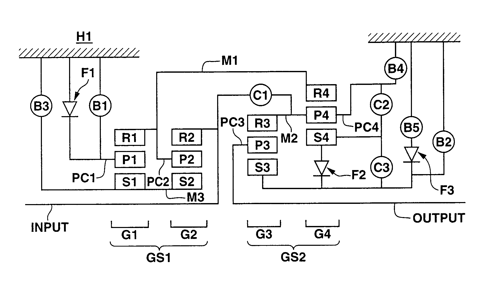
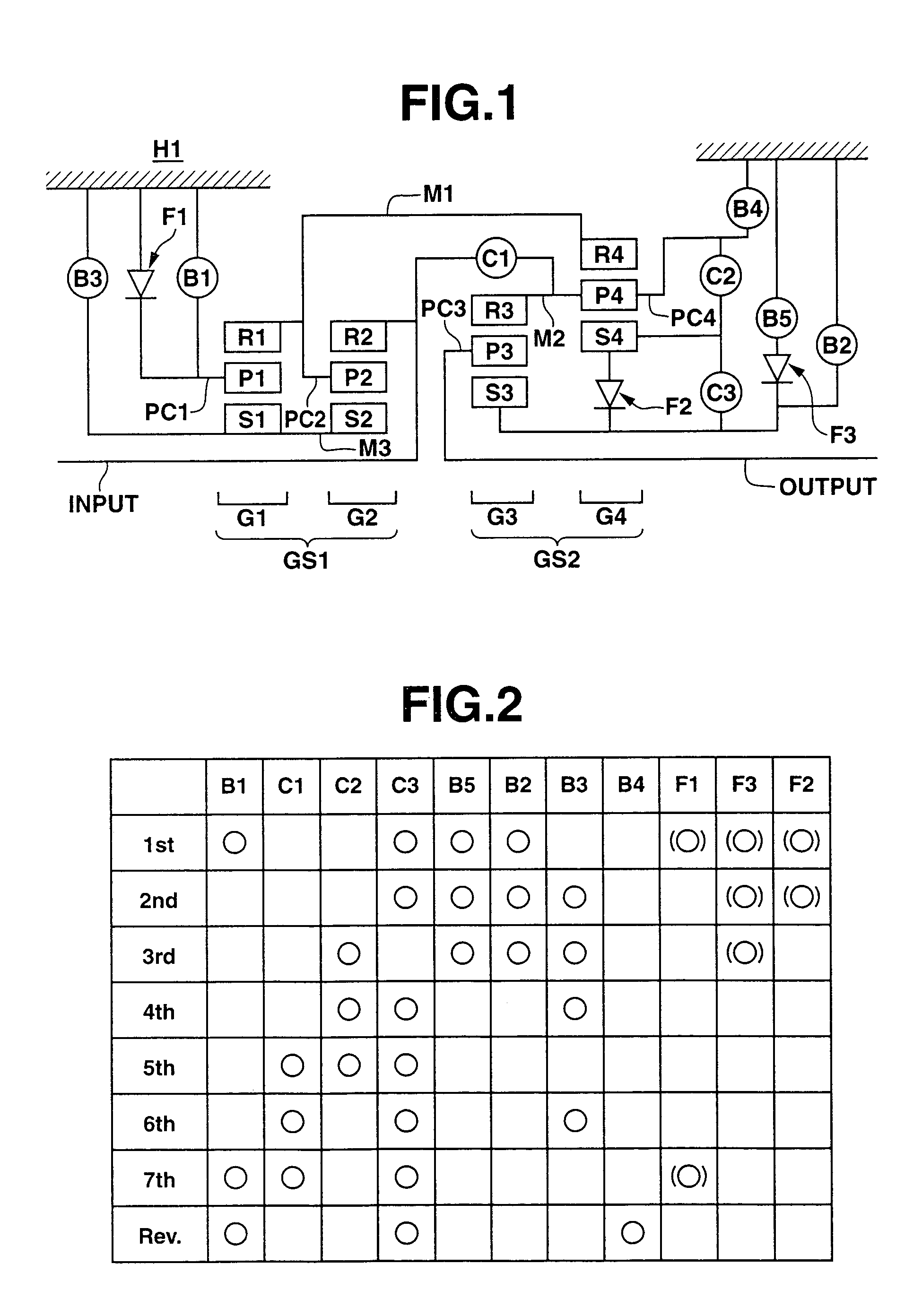
[0032]FIG. 1 is a schematic diagram depicting a power transmission mechanism of an automatic transmission for a front-engine, rear-drive vehicle, configured to establish seven forward speeds and one reverse speed, in accordance with the present invention. There are arranged a first planetary gearset GS1 including a first planetary gear G1 and a second planetary gear G2, nearer to an input shaft INPUT (on the left side of FIG. 1), and a second planetary gearset GS2 including a third planetary gear G3 and a fourth planetary gear G4, nearer to an output shaft OUTPUT (on the right side of FIG. 1). In a transmission housing H1 are mounted a plurality of torque transmitting devices. More specifically, a first clutch C1, a second clutch C2, a third clutch C3, a first brake B1, a second brake B2, a third brake B3, a fourth brake B4, and a fifth brake B5 are disposed in transmission housing H1. In addition, a plurality of one-way clutches including a first one-way clutch F1, a second one-way...

third embodiment

[0091]FIG. 19 is a schematic diagram depicting a power transmission mechanism of an automatic transmission for a front-engine, rear-drive vehicle, configured to establish seven forward speeds and one reverse speed, in accordance with the present invention. FIG. 20 is shows in tabular form clutch and brake engagements required to establish the seven forward speeds and the reverse speed in the power transmission mechanism of FIG. 19.

[0092]In addition to the constituent elements as employed in the first embodiment, this power transmission mechanism includes an eighth brake B8 and a fourth one-way clutch F4 in parallel to third brake B3. In this embodiment, eighth brake B8 is engaged while third brake B3 is engaged. However, it is not essential to engage both of the brakes. Only eighth brake B8 may be engaged in accordance with a desired capacity of torque transmission.

[0093]In the gear shift from the fourth speed to the fifth speed, the transmission controller disengages third brake B3...

fourth embodiment

[0094]FIG. 21 is a schematic diagram depicting a power transmission mechanism of an automatic transmission for a front-engine, rear-drive vehicle, configured to establish eight forward speeds and one reverse speed, in accordance with the present invention. FIG. 22 shows in tabular form clutch and brake engagements required to establish the eight forward speeds and the reverse speed in the power transmission mechanism of FIG. 21.

[0095]In addition to the constituent elements as employed in the second embodiment, this power transmission mechanism includes an eighth brake B8 and a fourth one-way clutch F4 in parallel to third brake B3. This transmission produces same effects as in the third embodiment.


PUM


Abstract

A power transmission mechanism for an automatic transmission, configured to establish seven or more forward speeds and one reverse speed. The power transmission mechanism includes four simple planetary gears, three connection members interconnecting two of the rotating members of the planetary gears, three clutches selectively connectable between two of the rotating members, and four brakes each operable to hold selectively against rotation one of the rotating members.

Description

BACKGROUND OF THE INVENTION[0001]The present invention relates generally to automatic transmissions for automotive vehicles, and more particularly to a power transmission mechanism for an automatic transmission, configured to establish seven or more forward speeds and one or more reverse speed.[0002]A Published Japanese Patent Application Publication No. 2000-266138 (hereinafter referred to as “JP2000-266138”) shows a power transmission mechanism for an automatic transmission, configured to establish seven forward speeds and one reverse speed. This power transmission mechanism includes a compound planetary gearset as an input section, a pair of planetary gears as an output section, three clutches, a one-way clutch, and four brakes. The compound planetary gearset on the input side includes a sun gear, a ring gear, a secondary ring gear, and a planet-pinion carrier supporting a short planet pinion in mesh with the secondary ring gear and a long planet pinion in mesh with the short pin...

Claims


Application Information

Patent Timeline
Patent Type & Authority Patents(United States)
IPC IPC(8): F16H3/62F16H3/66
CPCF16H3/66F16H2200/0056F16H2200/006F16H2200/2012
Inventor OGURI, KAZUOOKAMOTO, IKUO
Owner JATCO LTD
Why Eureka
Try Eureka