Beam deflecting method, beam deflector for scanning, ion implantation method, and ion implantation system

a beam deflector and beam deflector technology, applied in the field of beam deflector for scanning and beam deflector for deflecting charged particle beam, can solve the problems of large power consumption, difficult to generate magnetic field, large and complicated

Active Publication Date: 2006-11-21
SEN CORP AN SHI & AXCELIS
View PDF17 Cites 8 Cited by
  • Summary
  • Abstract
  • Description
  • Claims
  • Application Information

AI Technical Summary

Benefits of technology

[0010]It is an object of this invention to realize an electrostatic deflector that is practical and compact and that scans a large-diameter or large-current beam without defocus thereof.
[0033]In the beam deflector of the seventh aspect, it is preferable that each of the openings of the suppression and ground electrodes is formed into a rectangular shape with a large aspect ratio which is large in a direction of a horizontal beam width while one size larger than a vertical beam width in a direction of the vertical beam width so as to well suppress an electrical field.
[0037]In the beam deflector of the seventh aspect, by causing an electrical field in a direction perpendicular to a beam deflection plane at a center portion in the beam deflector for scanning to be slightly stronger than electrical fields in the other regions, consequently a beam profile after passing through the beam deflector for scanning is made excellent.

Problems solved by technology

However, the magnetic deflector has a demerit that a structure thereof tends to be large and complicated and further the power consumption thereof is large.
In addition, the magnetic deflector also has a demerit that the magnetic field tends to leak and, as a scanning frequency increases, it becomes more difficult to generate the magnetic field.
However, the electrostatic deflector has a demerit that a uniform electrical field is difficult to generate and the beam after deflection is inferior in quality as compared with that in the magnetic deflector.

Method used


Image

  • Beam deflecting method, beam deflector for scanning, ion implantation method, and ion implantation system
  • Beam deflecting method, beam deflector for scanning, ion implantation method, and ion implantation system
  • Beam deflecting method, beam deflector for scanning, ion implantation method, and ion implantation system

Examples


Embodiment Construction

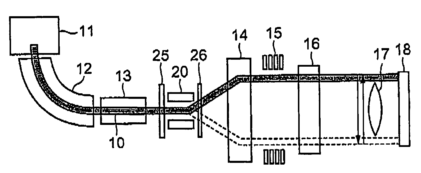
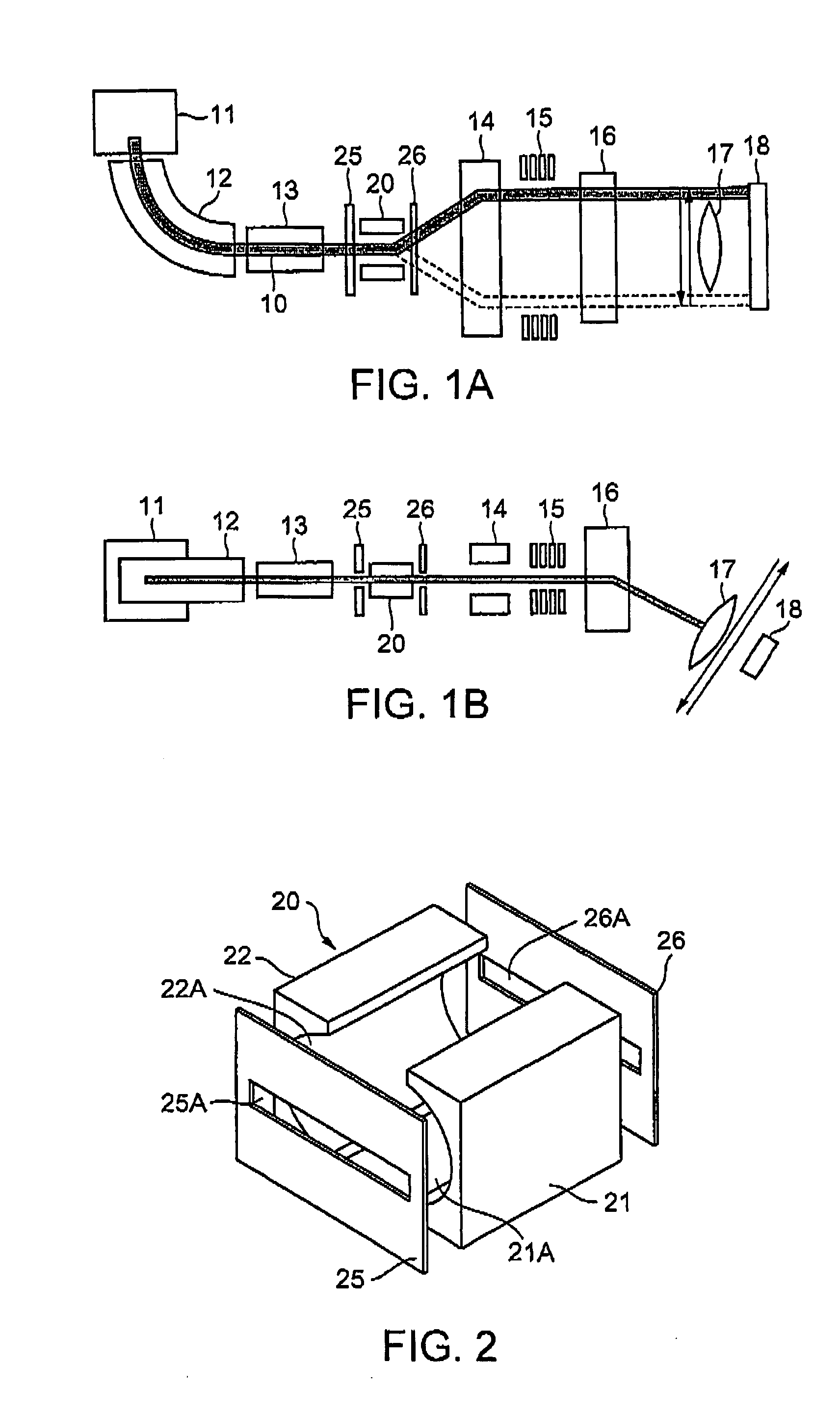
[0061]Referring to FIGS. 1A and 1B, description will be given about an embodiment wherein this invention is applied particularly to a single-wafer ion implantation system among those processing systems using charged particle beams. FIG. 1A is a plan view showing a schematic structure of the single-wafer ion implantation system, while FIG. 1B is a side view of FIG. 1A.

[0062]In FIGS. 1A and 1B, ions generated in an ion source 11 are extracted through an extraction electrode (not illustrated) as an ion beam (hereinafter referred to as a “beam”). The extracted beam is analyzed by a mass analysis electromagnet device 12 so that only a necessary ion species is selected. The beam composed of the selected ion is shaped into a beam having a required cross-sectional shape by a beam shaper 13. The beam shaper 13 is formed by a Q (Quadrupole)-lens and so on. The beam having a regular trajectory and the shaped cross-section is deflected in a direction parallel to the sheet surface of FIG. 1A by ...


PUM

PropertyMeasurementUnit
voltageaaaaaaaaaa
dc voltageaaaaaaaaaa
deflection angleaaaaaaaaaa

Abstract

A beam deflector for scanning performs deflecting of a charged particle beam having a regular trajectory in a vacuum space to thereby periodically change the trajectory of the charged particle beam. The beam deflector comprises a pair of deflection electrodes disposed so as to confront each inner electrode surface having a symmetrical concave extending in a direction of a beam trajectory.

Description

[0001]This application claims priority to prior Japanese patent application JP 2004-347298, the disclosure of which is incorporated herein by reference.BACKGROUND OF THE INVENTION[0002]This invention relates to a deflecting method for scanning and a deflector for deflecting a charged particle beam such as an ion beam with scanning. This invention particularly relates to a deflecting method and a deflector suitable for deflecting a charged particle beam with a relatively large current or a charged particle beam with a relatively large diameter. The charged particle beam with the relatively large diameter represents, for example, a charged particle beam having a flattened cross-sectional shape in which its horizontal width is greater than its vertical width. Note that “horizontal” which will hereinafter be referred to represents one axis in a plane in a direction perpendicular to a center axis of a beam trajectory and does not necessarily represent a horizontal axis. Likewise, “vertic...

Claims


Application Information

Patent Timeline
Patent Type & Authority Patents(United States)
IPC IPC(8): G01N23/00G21G5/00G21K7/00
CPCH01J37/1477H01J37/3171H01J37/08H01J37/147
Inventor MATSUSHITA, HIROSHIKABASAWA, MITSUAKIAMANO, YOSHITAKAKIMURA, YASUHIKOTSUKIHARA, MITSUKUNIMURAKAMI, JUNICHI
Owner SEN CORP AN SHI & AXCELIS
Why Eureka
Try Eureka