
Hockey stick

Inactive Publication Date: 2006-12-05
BAUER HOCKEY LLC
View PDF337 Cites 51 Cited by
  • Summary
  • Abstract
  • Description
  • Claims
  • Application Information

AI Technical Summary

Problems solved by technology

Moreover, the subjective nature inherent in this decision often results in one hockey player preferring a certain “feel” of a particular hockey stick while another hockey player preferring the “feel” of another hockey stick.

Method used


Image

  • Hockey stick
  • Hockey stick
  • Hockey stick

Examples


Embodiment Construction

[0027]Reference will now be made to the construction and operations of preferred embodiments of the present invention, examples of which are illustrated in the accompanying drawings. The following descriptions of the preferred embodiments of the present invention are only exemplary of the invention. The present invention is not limited to these embodiments, but may be realized by other embodiments.

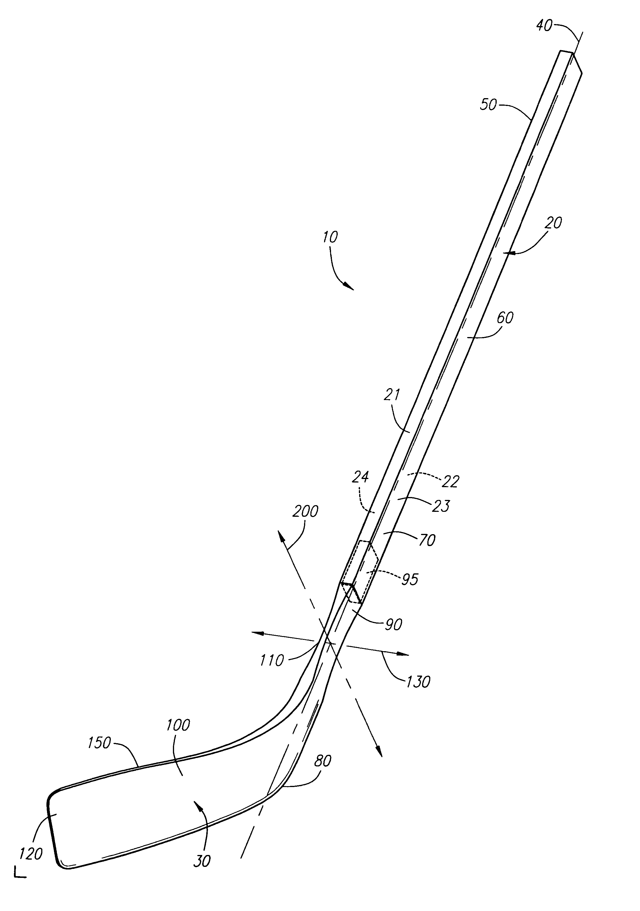
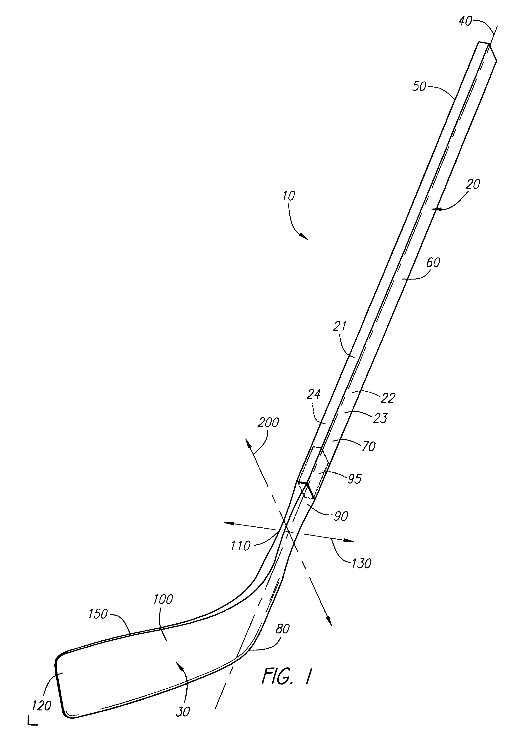
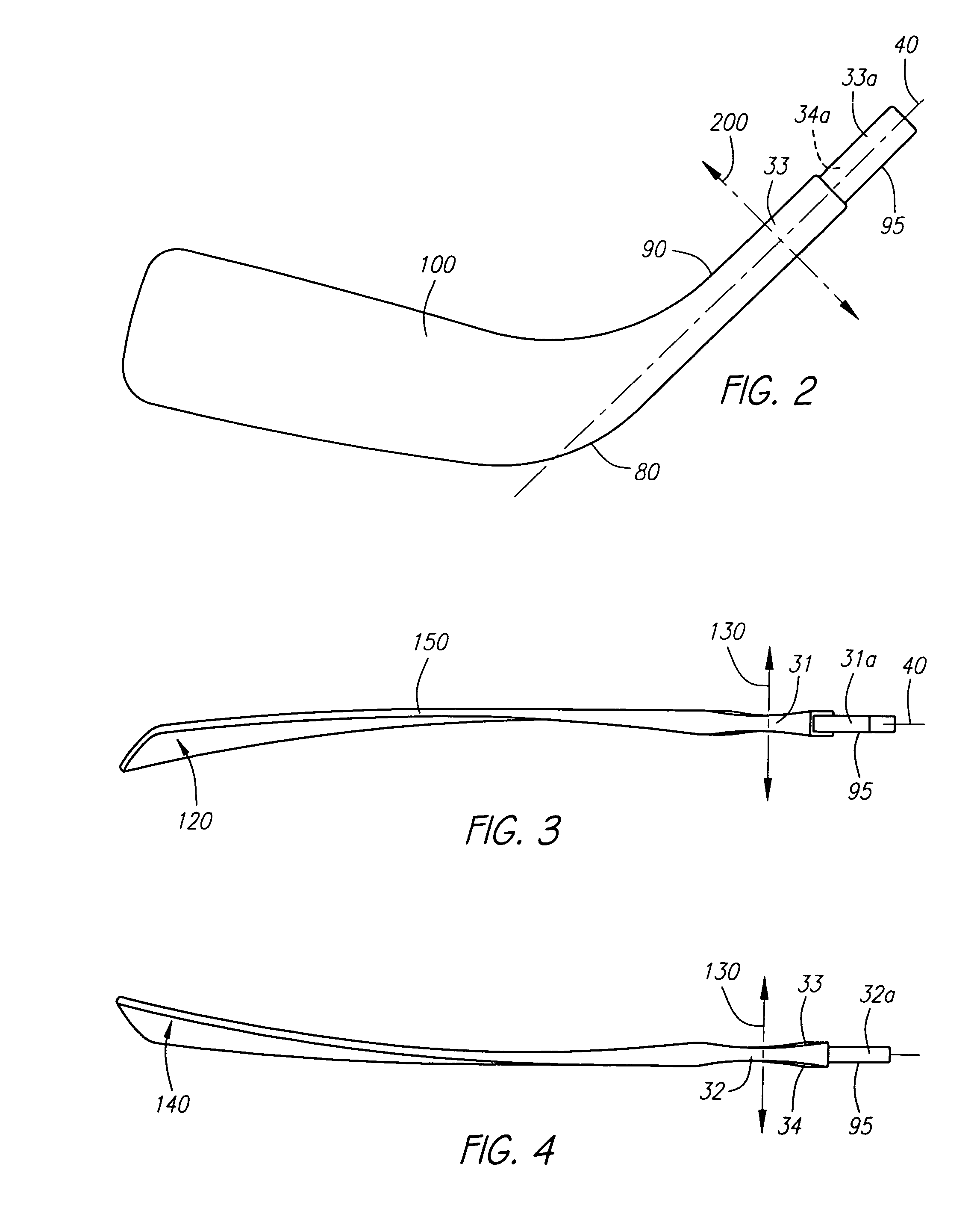
[0028]FIG. 1 is a diagram illustrating a hockey stick 10 in accordance with a preferred embodiment as disclosed herein. FIGS. 2–7 are diagrams illustrating from different perspectives and views the blade portion of the hockey stick illustrated in FIG. 1. As shown in FIGS. 1–7, a hockey stick 10 is comprised of a handle or shaft 20 and a blade 30. The shaft 20 is preferably comprised of a hollow tubular member having a top section 50, a middle section 60 and a bottom section 70. The cross-sectional area of the shaft 20 is generally rectangular throughout the longitudinal length of the shaft...


PUM


Abstract

A hockey stick comprising a blade and a shaft adapted to being joined together. The blade portion having an upper portion and a lower portion and a face. The upper portion being comprised of a defined region having a reduced width dimension in a direction that extends generally perpendicular from the face of the blade when measured relative to regions in the upper portion of the blade that border either side of the defined region. The defined region may also be comprised of a reduced longitudinal bending stiffness in a direction that extends generally perpendicular from the face of the blade when measured relative to regions in the upper portion of the blade that border either side of the defined region.

Description

CROSS-REFERENCE TO RELATED APPLICATIONS[0001]This application is a continuation of U.S. patent application Ser. No. 09 / 929,299 filed on Aug. 14, 2001 now abandoned, which is a continuation of U.S. patent application Ser. No. 09 / 479,429 filed on Jan. 7, 2000, now abandoned. Each of these two applications is hereby incorporated in their entirety be reference. This application claims the benefit of priority under 35 U.S.C. § 120 to both U.S. patent application Ser. No. 09 / 929,299 filed on Aug. 14, 2001 and U.S. patent application Ser. No. 09 / 479,429 filed on Jan. 7, 2000, now abandoned.FIELD OF THE INVENTION[0002]The field of the present invention relates to hockey sticks and the blades thereof.BACKGROUND OF THE INVENTION[0003]Generally, hockey sticks are comprised of a blade portion and a shaft or handle portion. Traditionally, these portions were permanently joined to one another. In more recent times, the blade and shaft have been constructed in a manner that facilitates the user's ...

Claims


Application Information

Patent Timeline
Patent Type & Authority Patents(United States)
IPC IPC(8): A63B59/14A63B49/10
CPCA63B59/14A63B49/106A63B53/02A63B59/0014A63B2209/02A63B2209/023A63B2243/0045A63B49/11A63B59/70A63B60/06A63B60/08A63B60/10A63B2102/24
Inventor GOLDSMITH, EDWARD MEASTON, JAMES L.
Owner BAUER HOCKEY LLC
Learn More