Slide latch

a slide latch and latch technology, applied in the field of slide latches, can solve the problems of easy corrosion and relatively complex assembly of conventional slide latches, and achieve the effect of reducing the amount of undesired movement of the latch

Active Publication Date: 2006-12-12
SOUTHCO
View PDF25 Cites 10 Cited by
  • Summary
  • Abstract
  • Description
  • Claims
  • Application Information

AI Technical Summary

Benefits of technology

[0009]The present invention in one embodiment comprises a latch housing, a lock plug which is configured to receive a key, a lock collar around the lock plug at the top portion thereof and a spring mounted in one end of the housing. A pawl on the housing of the latch which is configured and positioned to secure the first panel in which the latch is installed to a second panel when the latch is in the closed position. A biasing device such as a spring biases the latch so as to keep the latch in the fully closed position. The spring also acts as a biasing means in order to minimize undesired movement of the latch which may cause rattling of the latch when the latch is in an at rest or closed position.
[0010]A user can slide the latch to the closed position and lock the latch by using the key to rotate the lock plug to a locked position which also rotates the locking collar. When a user has so positioned the lock plug, the locking collar around the top portion of the lock plug blocks the sliding of the latch in the cutout portion of the first panel, thereby keeping the latch in the locked position. When a user rotates the key in the lock plug to the unlocked position, the portion of the locking collar which blocks sliding movement of the latch rotates away free and clear of the panel in which the latch is mounted. The latch can now be slid in a direction leading away from the pawl, thereby permitting sliding movement of the latch toward an unlocked position such that the pawl of the latch can clear the second panel or keeper on a second panel. The first panel can then be moved away from the second panel.
[0014]Another object of the invention is to provide a locking slide latch which does not present an electrical safety hazard as the lock plug of the present invention is totally enclosed in a housing formed from electrically nonconductive or electrically insulated material.

Problems solved by technology

Conventional slide latches are typically relatively complex to assemble and susceptible to corrosion.

Method used


Image

  • Slide latch
  • Slide latch
  • Slide latch

Examples


Embodiment Construction

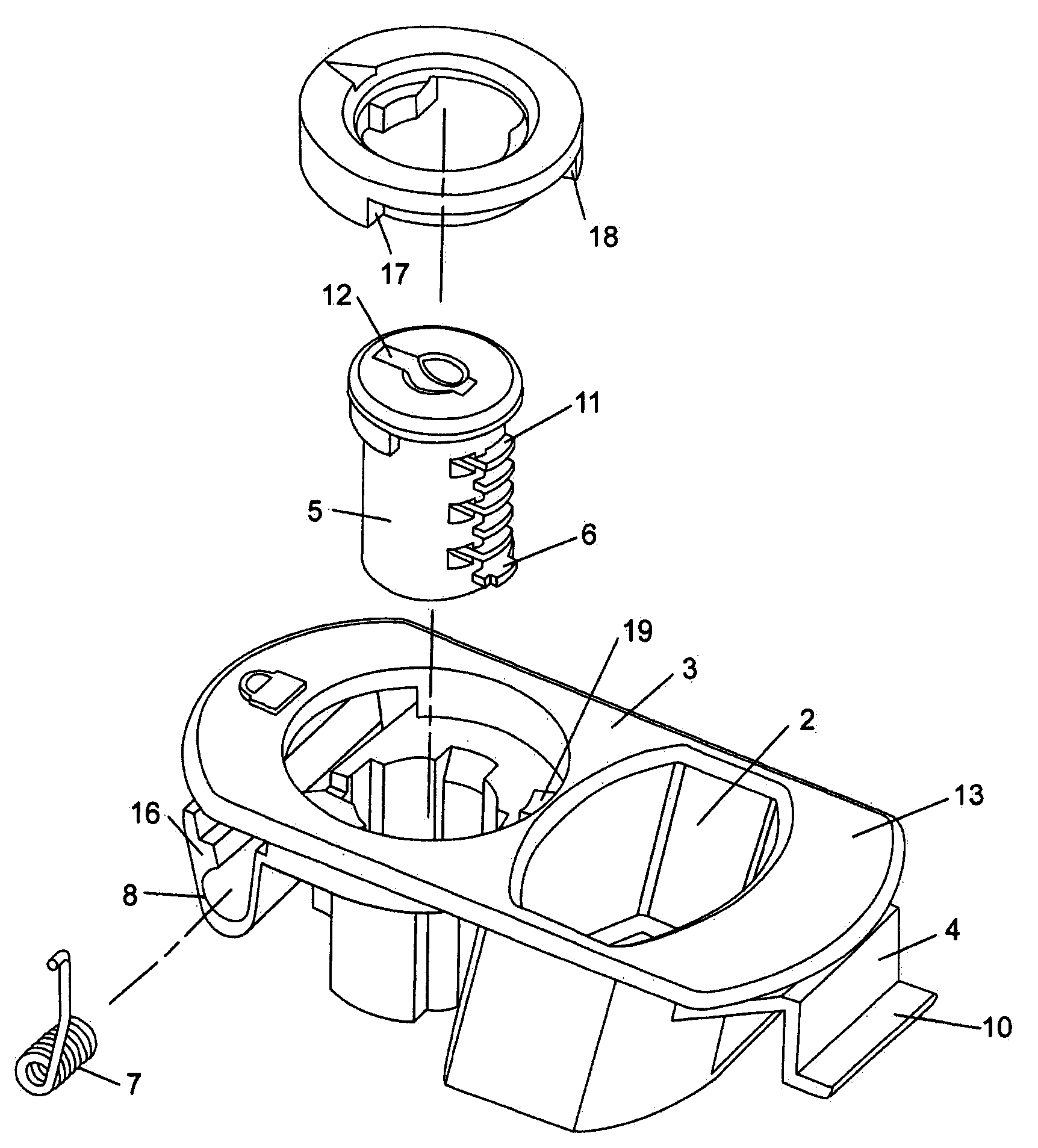
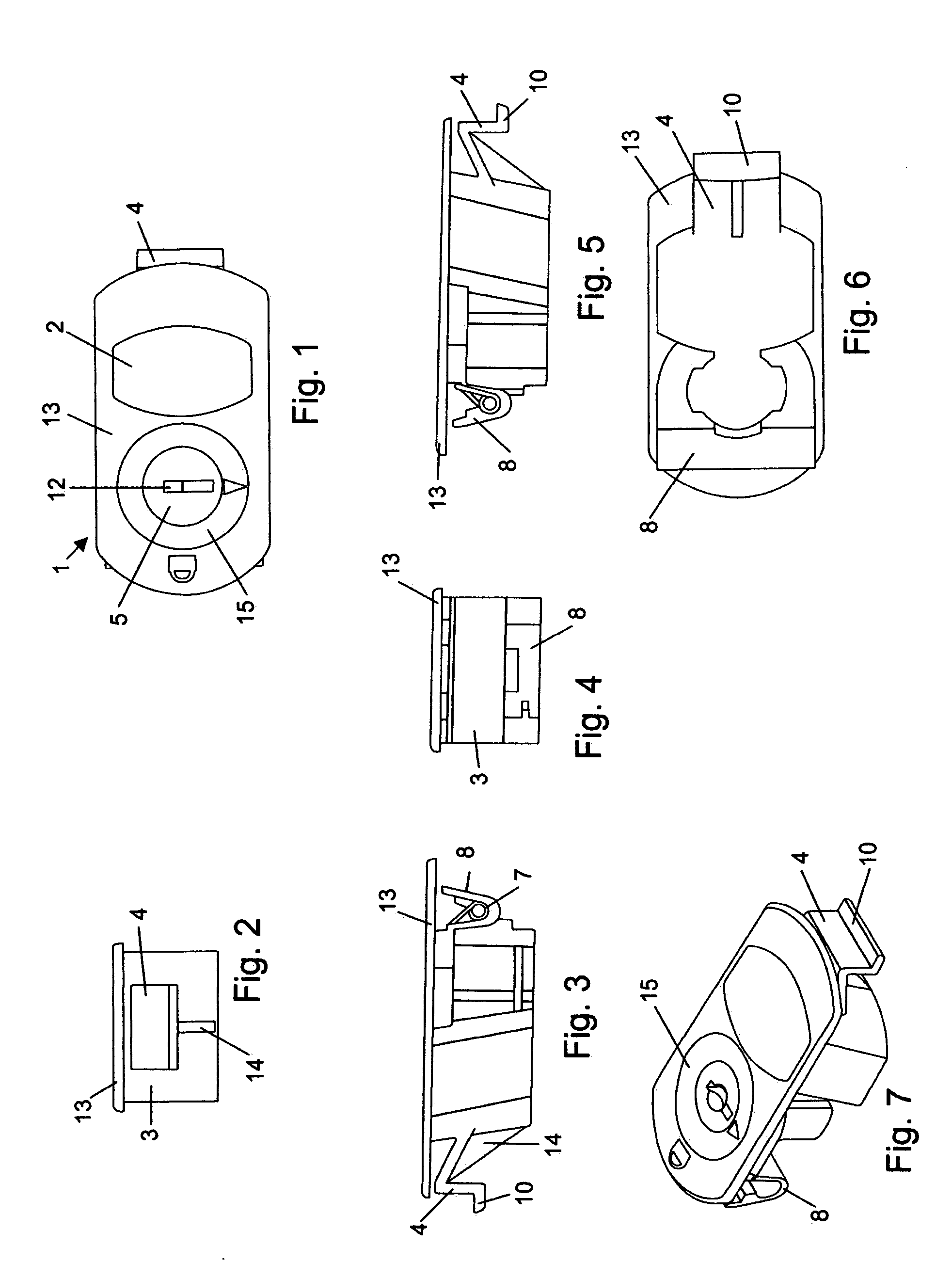
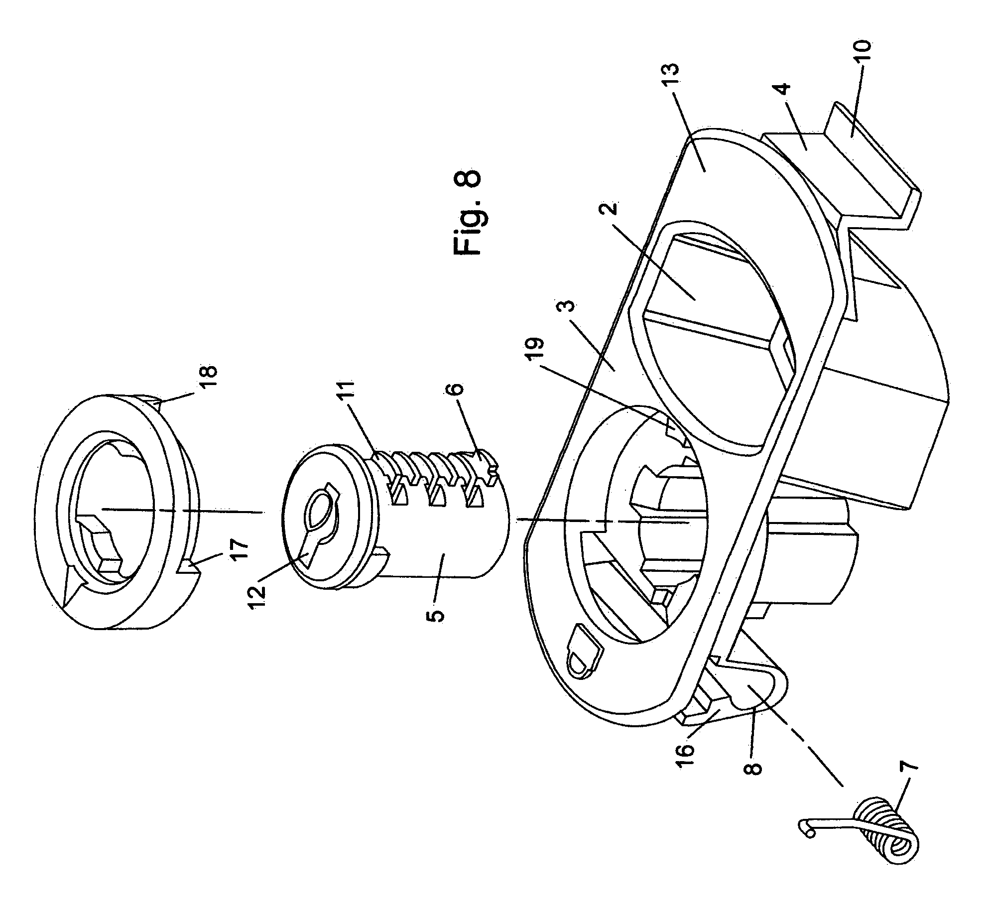
[0061]Referring now to the drawings in detail, wherein like reference numerals indicate like elements through the several views, there is shown in FIGS. 1–7, different views of a preferred embodiment of a latch 1 in accordance with the present invention shown with a housing 3, grip recess 2 for use by a user to slide the latch 1 and pawl 4 which upon sliding of the housing 3 engages a panel or keeper connected to a panel or prevents the pawl from moving past a keeper on the second panel. The housing 3 shown in FIG. 1 includes a flange 13 which fits up against first panel 9.

[0062]The term panel as used herein is defined broadly to include any structure or member, such as a frame or panel, that is capable of being fastened to the panel in which the slide latch of the present invention is installed.

[0063]A lock plug 5 is inserted into housing 103 which in turn preferably covers the bottom of lock plug 5 such that lock plug 5 can not be seen by a viewer as is readily apparent in the bot...


PUM


Abstract

The present invention relates to a lockable latch for securing together a first panel to a second panel or keeper on a second panel or frame. The latch has a housing, a lockplug configured for a key, a lock collar and a return spring. When a user turns a key to rotate the lockplug and thereby lock the lockplug, the lock collar rotates through 90 degrees and a portion thereof occupies the space or gap between an edge of the first panel and a portion of the latch housing configured and dimensioned to receive the edge of the first panel or frame. As a result, space between an edge of the housing and the first panel is taken up by a portion of the locking collar due to rotation of the locking collar in the housing.

Description

CROSS REFERENCE TO RELATED APPLICATIONS[0001]This application is a continuation-in-part of U.S. Ser. No. 10 / 744,140 filed on Dec. 22, 2003 now abandoned.BACKGROUND OF THE INVENTION[0002]The present invention relates to slide latches for doors, panels and the like. The latches incorporate a locking feature and are resistant to corrosion, making them useful in automotive, recreational vehicle, marine and other applications. The latch can be repeatedly latched and unlatched by a user who desires to fasten a first panel to which the latch is attached to a second panel or structure.[0003]Various types of slide latches are known. These latches are inserted in a cut-out opening of a first panel and are slidable in the plane of the first panel to engage a second panel or frame member. Conventional slide latches are typically relatively complex to assemble and susceptible to corrosion.[0004]A need exists for a latch which can provide an improvement over the prior art in that it will be less ...

Claims


Application Information

Patent Timeline
Patent Type & Authority Patents(United States)
IPC IPC(8): E05B13/10E05B9/08E05B13/00E05B25/00E05C1/10
CPCE05B9/086E05C1/10E05B13/10Y10S292/31Y10T70/5097Y10T70/5761Y10T292/0997Y10T70/5394
Inventor ANTONUCCI, JEFFNEALE, ROBERTRODRIGUEZ, ISMAEL
Owner SOUTHCO
Why Eureka
Try Eureka